Method and system for extracting natural gas hydrate through thermal jet flow
What is Al technical title?
Al technical title is built by PatSnap Al team. It summarizes the technical point description of the patent document.
A technology for natural gas and hydrates, used in the production of fluids, earth-moving drilling, wellbore/well components, etc.
Active Publication Date: 2015-12-09
CHINA UNIV OF PETROLEUM (BEIJING)
View PDF10 Cites 27 Cited by
Summary
Abstract
Description
Claims
Application Information
AI Technical Summary
This helps you quickly interpret patents by identifying the three key elements:
Problems solved by technology
Method used
Benefits of technology
Problems solved by technology
[0008] It can be seen from the above that there is currently no economical a...
Method used
Image
Click on the blue label to locate the original text in one second.
Reading with bidirectional positioning of images and text.
Examples
Embodiment 1
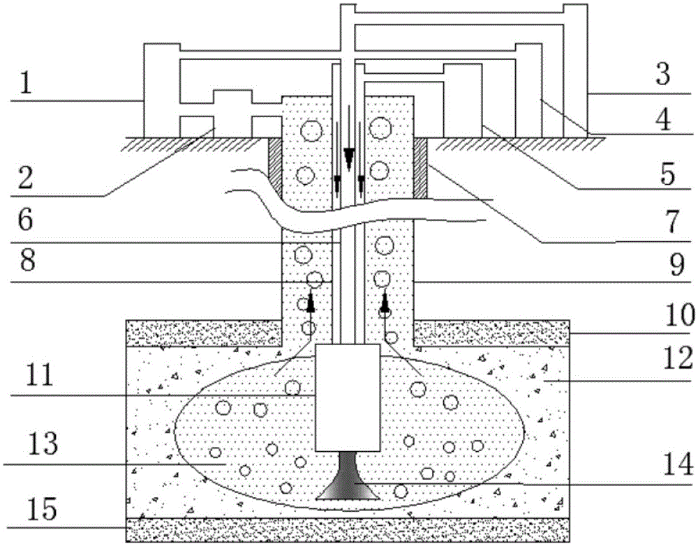
[0052] This embodiment provides a system for exploiting natural gas hydrates using thermal jets, such as figure 1 and figure 2 As shown, the system includes: combustion reaction device 11, coiled tubing inner tube 6, coiled tubing outer tube 8, cable 16, production casing 9, water supply device 3, fuel supply device 4, oxygen supply device 5, natural gas storage With the supply device 1, the gas-liquid separation device 2 and the pump set;
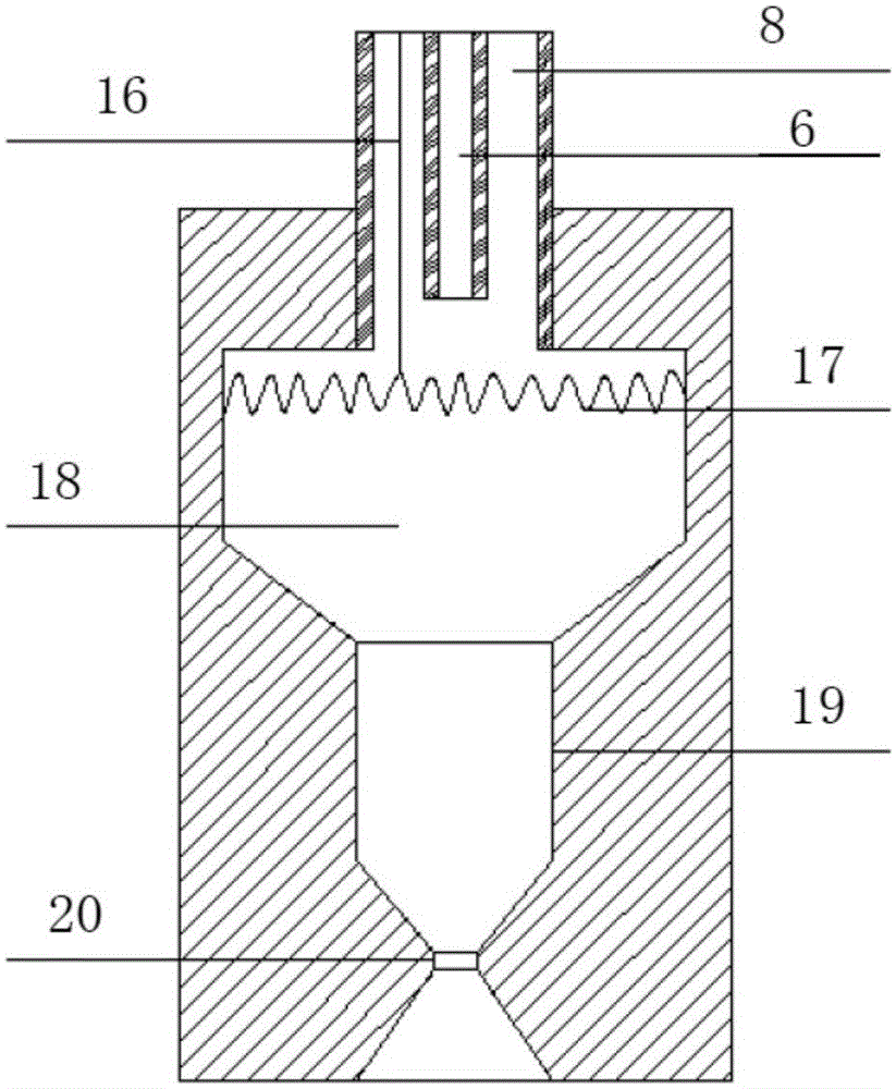
[0053] The combustion reaction device 11 is set at the target position in the well of the natural gas hydrate reservoir 12, the overlying formation 10 is above the natural gas hydrate reservoir 12, and the underburden formation 15 is below, and the combustion reaction device 11 includes a combustion reaction Chamber 18, the resistance wire 17 positioned in the combustion reaction chamber 18, the nozzle pipeline 19 positioned at the bottom of the combustion reaction chamber 18, and the nozzle outlet 20, the nozzle outlet 20 is a gradually...
Embodiment 2
[0058] This embodiment provides a method for exploiting natural gas hydrates using thermal jetting. The method uses the system provided in Embodiment 1, which includes the following steps:
[0059] Use thermal jet to drill multi-branch wells to different layers of natural gas hydrate reservoir 12. Above the natural gas hydrate reservoir 12 is the overlying stratum 10, and below it is the underlying stratum 15. For drilling through thermal jet, please refer to CN103790516A The drilling method disclosed in;
[0060] The combustion reaction device 11 is placed under the target position of each branch well, and the combustion reaction device 11 comprises a combustion reaction 18, a resistance wire 17 positioned in the combustion reaction chamber 18, a nozzle pipeline 19 positioned at the bottom of the combustion reaction chamber 18 and a nozzle outlet 20, the nozzle outlet 20 is a tapered outlet with gradual divergence;
[0061] Lower the production casing 9 from the ground to th...
PUM
Abstract
The invention provides a method and system for extracting natural gas hydrate through thermal jet flow. The method includes the steps that a combustion reaction device is lowered to a downhole target position of a natural gas hydrate reservoir, oxygen and fuel are injected into the downhole target position, the combustion reaction device is powered on, ignition is performed, combustion products are jet out of the combustion reaction device to form high-speed jet flow, the jet flow and heat generated during combustion act on the natural gas hydrate reservoir so that natural gas hydrate can be decomposed, and decomposed natural gas returns upwards to the ground; the amount of injected fuel is gradually reduced till injection stops, meanwhile part of the natural gas returning upwards to the ground and water are injected and mixed with oxygen for continuous combustion, and natural gas hydrate can be furthermore decomposed. The system at least comprises the combustion reaction device, a continuous oil tube inner tube, a continuous oil tube outer tube, a cable, a production sleeve, a water supply device, a fuel supplying device, an oxygen supplying device, a natural gas storing, collecting and supplying device and a pump set. The method and system for extracting natural gas hydrate through thermal jet flow have the advantages that extracting cost is low, extracting efficiency is high and the system structure is simple.
Description
technical field [0001] The invention relates to a method and a system for exploiting natural gas hydrate by utilizing thermal jet flow, and belongs to the technical field of energy exploitation. Background technique [0002] At present, with the continuous development of the global economy, the demand for energy is further increasing. With the development, conventional oil and gas reserves continue to decline, and the difficulty of mining continues to increase. Natural gas hydrates are widely distributed in nature, and mainly exist in the continental shelf at a depth of 0-1500m on the seabed and the permafrost in the Arctic and other places. According to estimates by relevant experts, the total amount of natural gas hydrates is huge, and the total resources are twice the current total resources of coal and oil and gas. At present, natural gas hydrate deposits have been discovered in many countries. my country has also successfully drilled combustible ice in the Shenhu area ...
Claims
Application Information
Patent Timeline
Application Date:The date an application was filed.
Publication Date:The date a patent or application was officially published.
First Publication Date:The earliest publication date of a patent with the same application number.
Issue Date:Publication date of the patent grant document.
PCT Entry Date:The Entry date of PCT National Phase.
Estimated Expiry Date:The statutory expiry date of a patent right according to the Patent Law, and it is the longest term of protection that the patent right can achieve without the termination of the patent right due to other reasons(Term extension factor has been taken into account ).
Invalid Date:Actual expiry date is based on effective date or publication date of legal transaction data of invalid patent.