Combustion chamber and gas engine

A combustion chamber and cylinder head technology, applied to combustion engines, internal combustion piston engines, engine components, etc., can solve problems that affect the formation of tumble flow in the combustion chamber, accelerate combustion, and difficulty

Active Publication Date: 2021-09-17
WEICHAI POWER CO LTD
View PDF5 Cites 2 Cited by
  • Summary
  • Abstract
  • Description
  • Claims
  • Application Information

AI Technical Summary

Problems solved by technology

Thanks to the squish movement at the end of compression, the flame spreads faster laterally, but the flame spreads slowly in the combustion chamber 01, which is not conducive to the premixed combustion of gaseous fuels, such as figure 1 As shown, the rectangular dotted frame area near the spark plug 03 is the flame propagation low speed zone 02. The horizontal direction mentioned in this article refers to the radial direction of the cylinder, and the longitudinal direction refers to the axial direction of the cylinder.
[0004] In addition, for a four-valve engine, in the prior art scheme, the area below the c

Method used


Image

  • Combustion chamber and gas engine
  • Combustion chamber and gas engine
  • Combustion chamber and gas engine

Examples


Embodiment Construction

[0040] The following will clearly and completely describe the technical solutions in the embodiments of the present invention with reference to the accompanying drawings in the embodiments of the present invention. Obviously, the described embodiments are only some, not all, embodiments of the present invention. Based on the embodiments of the present invention, all other embodiments obtained by persons of ordinary skill in the art without making creative efforts belong to the protection scope of the present invention.

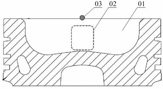
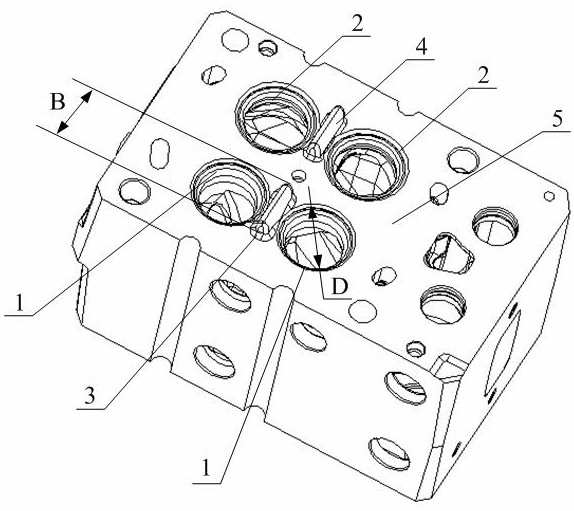
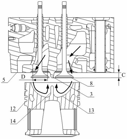
[0041] Please refer to Figure 2 to Figure 6 , figure 2 It is a structural schematic diagram of a cylinder head in a specific embodiment of the present invention; image 3 It is a schematic diagram of the air intake effect of the combustion chamber in a specific embodiment of the present invention; Figure 4 It is an enlarged schematic diagram of the exhaust throat and the cooling water jacket in the specific embodiment of the present invention; Figure 5 It...


PUM


Abstract

The invention discloses a combustion chamber and a gas engine. The combustion chamber is applied to the gas engine with at least two air inlet throats and at least two exhaust throats; the combustion chamber comprises a combustion chamber pit which is located at the top of a piston and is sunken downwards relative to the upper top surface of the piston, and the intersecting line of the combustion chamber pit and the longitudinal section of the piston is an arc line; a partition convex rib is arranged in the combustion chamber pit, and the partition convex rib extends upwards from the bottom of the combustion chamber pit and divides the combustion chamber pit into two flow guide pits; each flow guide pit comprises an incident flow guide part located below the corresponding air inlet throat and an emergent flow guide part located below the exhaust throat; and the joints of the wall surfaces of the flow guide pits and the partition convex ribs are smooth transition surfaces. Due to the fact that the combustion chamber pit is divided into the two flow guide pits by the partition convex rib, inlet air of the air inlet throats on the two sides forms two strands of large-scale tumble motion opposite in rotation direction in the combustion chamber, improvement of turbulent kinetic energy in the last stage of compression is facilitated, and rapid combustion of the engine is facilitated.

Description

technical field [0001] The invention relates to the technical field of engines, in particular to a combustion chamber and a gas engine. Background technique [0002] With the development of gas engine technology, more and more engine manufacturers have begun to design and develop gas engines based on diesel engines. Due to the particularity of the combustion method of the diesel engine, it is necessary for the combustion chamber of the engine to organize the air flow to generate a sufficient swirl ratio during the intake process. However, the gas engine does not need too much vortex, but needs to organize the air flow to form a tumble flow perpendicular to the central axis of the rotation and the central axis of the cylinder liner. That is to say, for a gas engine, only by effectively generating sufficient tumble flow can the purpose of optimizing combustion be achieved. [0003] The piston and cylinder head structure of the existing gas engine is generally modified on the...

Claims


Application Information

Patent Timeline
IPC IPC(8): F02B23/06F02F3/26F02F1/42
CPCF02B23/0621F02F3/26F02F1/4285Y02T10/12
Inventor 吕顺李卫高克营唐国鹏钟绍海
Owner WEICHAI POWER CO LTD
Why Eureka
Try Eureka