Quick connecting structure for rotating shaft of speed reducer

A quick connection and reducer technology, applied in the direction of couplings, mechanical equipment, rigid shaft couplings, etc., can solve the troublesome installation and operation of split couplings, and it is difficult to ensure the synchronous rotation of the motor shaft and the input shaft of the reducer, etc. problems, to achieve the effect of improving convenience and ensuring the clamping effect

Inactive Publication Date: 2021-09-17
武汉荣誉机电设备工程有限公司
View PDF0 Cites 1 Cited by
  • Summary
  • Abstract
  • Description
  • Claims
  • Application Information

AI Technical Summary

Problems solved by technology

[0005] The invention provides a fast connection structure for the rotating shaft of the reducer, the purpose of which is to solve the problem of troublesome installation and operation of the split type coupling when the motor shaft and the input shaft of the reducer are connected by the split type coupling during the quality inspection process of the reducer , and it is difficult to ensure that the motor shaft and the input shaft of the reducer rotate synchronously

Method used


Image

  • Quick connecting structure for rotating shaft of speed reducer
  • Quick connecting structure for rotating shaft of speed reducer
  • Quick connecting structure for rotating shaft of speed reducer

Examples


Embodiment Construction

[0033]The embodiments of the present invention will be described in detail below with reference to the accompanying drawings, but the present invention can be implemented in many different ways defined and covered by the claims.

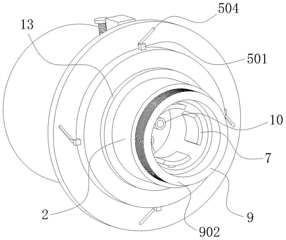
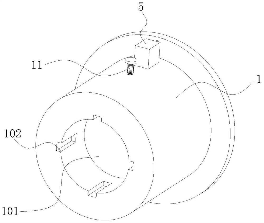
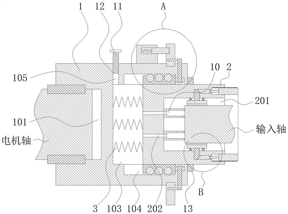
[0034] like Figure 1 to Figure 6 As shown, this embodiment provides a quick connection structure for the shaft of the reducer, including a cylindrical installation cylinder 1, and one end surface of the installation cylinder 1 is provided with a first circular groove 101 coincident with its axis, and the first circular groove 101 Several key grooves 102 are formed on the peripheral surface along its circumferential direction, and the key grooves 102 are axially arranged along the first circular groove 101 . The other end surface of the mounting cylinder 1 is provided with a second circular groove 103 coincident with its axis, and a sleeve 2 coincident with its axis is slidably fitted in the second circular groove 103 along its axial direction. A su...


PUM


Abstract

The invention belongs to the technical field of speed reducers, and particularly relates to a quick connecting structure for a rotating shaft of a speed reducer. The quick connecting structure comprises a mounting cylinder, a first circular groove, a key groove, a second circular groove and a guide groove are formed in the mounting cylinder, and a sleeve is arranged in the second circular groove in a sliding fit mode; a third circular groove is formed in the sleeve, a guide block is installed on the sleeve, a plurality of clamping blocks are installed on the third circular groove, a clamping plate is installed at the end of each clamping block, a reset spring is fixedly connected between each clamping plate and the third circular groove, and an auxiliary clamping mechanism is arranged on the sleeve. In the quality detection process of the speed reducer, compared with a split type coupler, the operation convenience is improved, and it can be guaranteed that a motor shaft and an input shaft of the speed reducer rotate synchronously.

Description

technical field [0001] The invention belongs to the technical field of reducers, and in particular relates to a fast connection structure of a rotating shaft of a reducer. Background technique [0002] The reducer is an independent component consisting of gear transmission, worm transmission, and gear-worm transmission enclosed in a rigid shell. It is often used as a reduction transmission device between the prime mover and the working machine. The reducer plays the role of matching speed and transmitting torque between the prime mover and the working machine or the actuator, and is widely used in modern machinery. The reducer includes an input shaft and an output shaft. The input shaft of the reducer is connected to the motor shaft through a coupling. When working, the motor drives the input shaft of the reducer to rotate, and after the internal deceleration of the reducer drives the output shaft of the reducer to rotate, thereby driving the external transmission turn. Af...

Claims


Application Information

Patent Timeline
Patent Type & Authority Applications(China)
IPC IPC(8): F16H57/00F16D1/04
CPCF16H57/0025F16D1/04
Inventor 夏超
Owner 武汉荣誉机电设备工程有限公司
Why Eureka
Try Eureka