
Sanding equipment based on horizontal machine tool

A machine tool and sanding technology, which is applied to the parts of grinding machine tools, grinding/polishing equipment, metal processing equipment, etc., can solve the problems of increased work intensity, large space, and low processing efficiency.

Inactive Publication Date: 2021-09-21
FUJIAN LIXIN SHIP ENG CO LTD
View PDF9 Cites 0 Cited by
  • Summary
  • Abstract
  • Description
  • Claims
  • Application Information

AI Technical Summary

Problems solved by technology

However, this technical solution requires a large space, and can only sand the two sides of the shaft body of the stern shaft at one time, resulting in low processing efficiency and increased work intensity of the staff.

Method used


Image

  • Sanding equipment based on horizontal machine tool
  • Sanding equipment based on horizontal machine tool
  • Sanding equipment based on horizontal machine tool

Examples


Embodiment 1

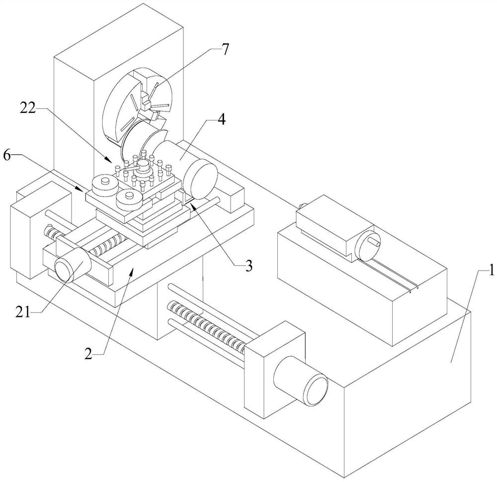
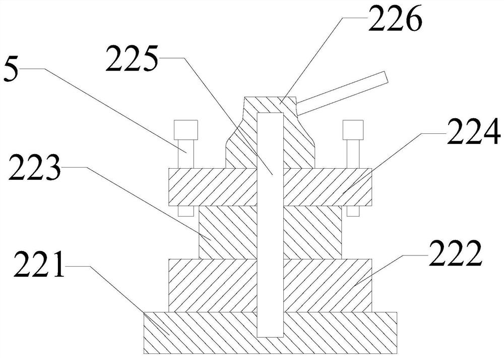
[0060] Please refer to Figure 1 to Figure 3 As shown, a sanding equipment based on a horizontal machine tool includes a lathe body 1, a support hanger 2, a mounting frame 3 and a sander 4; the support hanger 2 is arranged on the slide box of the lathe body 1, The support hanger 2 includes a linear slide 21 and a clamp 22, and the travel direction of the slide 21 of the linear slide 21 is perpendicular to the travel direction of the slide box of the lathe body 1; the clamp 22 includes a base 221 and a rotating seat 222 , a support block 223, a clamping plate 224, a threaded rod 225 and a threaded handle 226; the base 221 is arranged on the slide table of the linear slide table 21; the rotating seat 222 is placed on the top surface of the base 221; the The support block 223 is fixedly connected on the upper surface of the rotating seat 222; the lower surface of the clamping plate 224 is fixedly connected with the support block 223, and the clamping plate 224 is provided with a ...

Embodiment 2

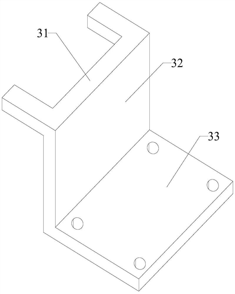
[0062] Please refer to figure 1 and Figure 4 As shown, the sanding equipment based on the horizontal machine tool also includes a balance device 6, the balance device 6 includes a load plate 61 and a weight block 62, one side of the load plate 61 can be inserted between the rotating seat 222 and the clamping plate 224 between, and tighten the fastening bolts 5 to fix on the support hanger 2; the weight block 62 can be placed on the load plate 61. The grinding wheel of the sander 4 is provided with a grinding wheel guard. The chuck of the lathe body 1 is provided with reserved installation grooves 7 at radial intervals. The lower end surface of the fastening bolt 5 is provided with a rubber pad.

[0063] To sum up, the present invention provides a sanding equipment based on a horizontal machine tool. A support hanger is added to the horizontal machine tool, and the installation frame is inserted between the rotating seat and the clamping plate, and then the fastening bolt i...


PUM


Abstract

The invention discloses sanding equipment based on a horizontal machine tool. The sanding equipment comprises a lathe body, a supporting hanging tool, a mounting frame and a sanding machine. The supporting hanging tool is arranged on a sliding box of the lathe body and comprises a linear sliding table and a clamp, and the sliding table stroke direction of the linear sliding table is perpendicular to the sliding box stroke direction of the lathe body. The clamp comprises a base, a rotating seat, a supporting block, a clamping plate, a threaded rod and a threaded handle. The base is arranged on a sliding table of the linear sliding table; the rotating seat is placed on the top surface of the base; the supporting block is fixedly arranged between the rotating seat and the clamping plate; a fastening bolt is arranged on the clamping plate along the contour edge; the threaded rod is mounted on the base, and one end of the threaded rod extends out of the upper surface of the clamping plate; the threaded handle is in threaded connection with the threaded rod; the mounting rack can be inserted between the rotating seat and the clamping plate, and is fixed on the supporting hanger by screwing the fastening bolt; and the sanding machine is fixedly mounted on the mounting frame. The sanding equipment can finish sanding of the surface of a stern shaft at a time.

Description

technical field [0001] The invention relates to the technical field of ship stern shaft sanding, in particular to a sanding device based on a horizontal machine tool. Background technique [0002] The stern shaft is also called the tail shaft. The stern shaft is the last shaft in the shaft system. The flange at the head end is connected to the flange of the intermediate shaft with tight fitting bolts; the tail end is conical and used to install the propeller. Refer to patent CN202021427520.8, which discloses "a tail shaft calendering process mechanism". The polished cover plate sands the surface of the stern shaft. However, this technical solution requires a large space, and can only sand both sides of the shaft body of the stern shaft at one time, resulting in low processing efficiency and increased work intensity of the staff. Contents of the invention [0003] The technical problem to be solved by the present invention is to provide a sanding equipment based on a hor...

Claims


Application Information

Patent Timeline
Patent Type & Authority Applications(China)
IPC IPC(8): B24B5/04B24B5/14B24B41/02B24B41/00
CPCB24B5/04B24B5/14B24B41/02B24B41/00
Inventor 陈立新刘元必
Owner FUJIAN LIXIN SHIP ENG CO LTD
Learn More