Material storage bin

A technology for storage bins and materials, applied in the direction of transporting passenger cars, tank cars, railway car body parts, etc., can solve the problems of large blocks, high hardness, and low moisture content of materials

Active Publication Date: 2021-09-21
浙江物产环能浦江热电有限公司
View PDF7 Cites 2 Cited by
  • Summary
  • Abstract
  • Description
  • Claims
  • Application Information

AI Technical Summary

Problems solved by technology

During the conveying process, two situations often occur. One is that due to the high water content of the material, the viscosity is also high, and agglomeration and adhesion between the materials will occur, resulting in the formation

Method used


Image

  • Material storage bin
  • Material storage bin
  • Material storage bin

Examples


Embodiment 1

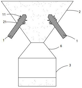
[0027] see Figure 1-3 , this embodiment provides a material storage bin, including a drive assembly, a frame (not shown in the figure), an electric heating rod 1, a feeding funnel 2 and a collection basin 3,

[0028] The feeding funnel 2 and the collecting basin 3 are all installed on the frame, and the collecting basin 3 is located below the discharging funnel 2, and the material is transported to the collecting basin 3 through the discharging funnel 2 under the action of gravity, so the discharging funnel 2 It is the necessary road section in the process of conveying materials to the collection basin 3 .

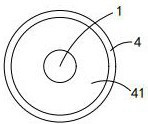
[0029] The side wall of the feeding funnel 2 is provided with an active hole 21 that matches the shape of the electric heating rod 1. The electric heating rod 1 is plugged into the active hole 21, and the driving component is transmitted to the electric heating rod 1, thereby controlling the electric heating rod 1 to move in the active hole 21. Move, so that the electric...

Embodiment 2

[0049] The difference between this embodiment and Embodiment 1 is that the material storage bin also includes a beating assembly, the beating assembly is installed on the frame and is located below the feeding funnel 2, and the beating assembly is carried out on the bottom outer wall of the feeding funnel 2. Beating, so that the fragmented material can enter the collection basin more smoothly.

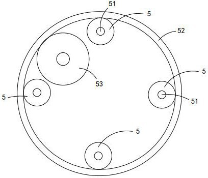
[0050] The beating assembly includes a rotating ring 7 , a beating rod 72 and a return spring 73 .

[0051] The top of the rotating ring 7 protrudes upwards to form an annular wave-shaped projection 71, and the rotating ring 7 is also rotatably mounted on the frame. Specifically, the frame can be provided with a second annular slide rail 74 below the rotating ring 7 through a connecting rod, and the bottom of the rotating ring 7 protrudes downward to form an annular slider, which is arranged on the second annular slide In the rail 74, the rotation process of the rotating ring 7 is sup...


PUM


Abstract

The invention discloses a material storage bin. The material storage bin comprises a driving assembly, a rack, electrical bars, a discharging hopper and a material collecting basin arranged below the discharging hopper, the discharging hopper and the material collecting basin are both installed on the rack, movable holes matched with the electrical bars in shape are formed in the side wall of the discharging hopper, the electrical bars are inserted into the movable holes, and the driving assembly controls the electrical bars to move at the movable holes. The electrical bars move on the discharging hopper so that the electrical bars can collide with blocky materials in the discharging hopper, the hard blocky materials are crushed, and the size of the blocky materials with high hardness is reduced; and as the viscosity of the blocky materials is reduced overall in the heating process, the crushed materials are not prone to agglomerate again.

Description

technical field [0001] The invention relates to a material storage bin, which belongs to the field of material storage. Background technique [0002] Blocky material is a solid material with a certain degree of water content, which itself has a certain degree of viscosity and hardness, and is generally transported to the collection basin 3 through a funnel. During the conveying process, two situations often occur. One is that due to the high water content of the material, the viscosity is also high, and agglomeration and adhesion between the materials will occur, resulting in the formation of large pieces of material, causing the funnel to be blocked. The other is The water content of the material is very small and the hardness is very high. Once the material itself is large, it is easy to cause the funnel to be blocked. Contents of the invention [0003] The technical problem to be solved by the present invention is to provide a material storage bin by overcoming the def...

Claims


Application Information

Patent Timeline
IPC IPC(8): B65D88/66B65D88/74B65B39/00B65B63/08
CPCB65D88/66B65D88/744B65B39/00B65B63/08
Inventor 冯一帆卓晓龙方自动余晓华郭晨星黄先蛟
Owner 浙江物产环能浦江热电有限公司
Why Eureka
Try Eureka