Driving mechanism motion direction conversion device and method

A technology of motion direction and driving mechanism, which is applied in the direction of power control mechanism, wing fan control mechanism, wing fan suspension device, etc., can solve the problem that extrusion force cannot produce the direction force of the Sierra, cannot satisfy customers, and Sierra Caton and other problems, to achieve the effect of solving the door closed tightly, the structure is small and reasonable, and the degree of wear and tear is reduced

Inactive Publication Date: 2021-09-21
金湖县金宇客车门泵厂
View PDF0 Cites 0 Cited by
  • Summary
  • Abstract
  • Description
  • Claims
  • Application Information

AI Technical Summary

Problems solved by technology

[0003] The above method will bring the following problems: 1. If the customer requests to increase the distance of the sliding door, when the sliding door is required to be vertically sliding, the upper guide rail needs to be made 90 degrees in the curve, and the extrusion force cannot produce the direction force of the sliding door, resulting in Unable to move the Sierra, that is, the existing products cannot be made into a vertical Sierra, which cannot meet the needs of customers;
[0004] 2. Since the force in the movement direction of the plug comes from the component force of the power source, the generated plug force is very small, resulting in poor sealing of the lower device behind the plug. Similarly, if the power source drive has reached the bottom, inflate in the opposite direction to meet the needs When the air pressure is pushed or pulled, it takes a certain amount of time, causing the Sierra to freeze;
[0005] 3. The power source is fixed on the movable frame, and the reaction force of the push-pull force of the cylinder all acts on the movable frame, causing the movable frame to be easily deformed;
[0006] 4. Since the pull force of the plug comes from the component force of the power source, to increase the pull force of the plug, the diameter of the cylinder or the air pressure or the slope of the upper track must be increased, which will increase the pressure on the inner slope of the upper guide rail and easily damage the slope of the upper guide rail , and increasing the diameter of the cylinder, it may not be able to meet the overall installation requirements of the device, which will bring difficulties to the design of the overall device

Method used


Image

  • Driving mechanism motion direction conversion device and method
  • Driving mechanism motion direction conversion device and method
  • Driving mechanism motion direction conversion device and method

Examples


Embodiment 1

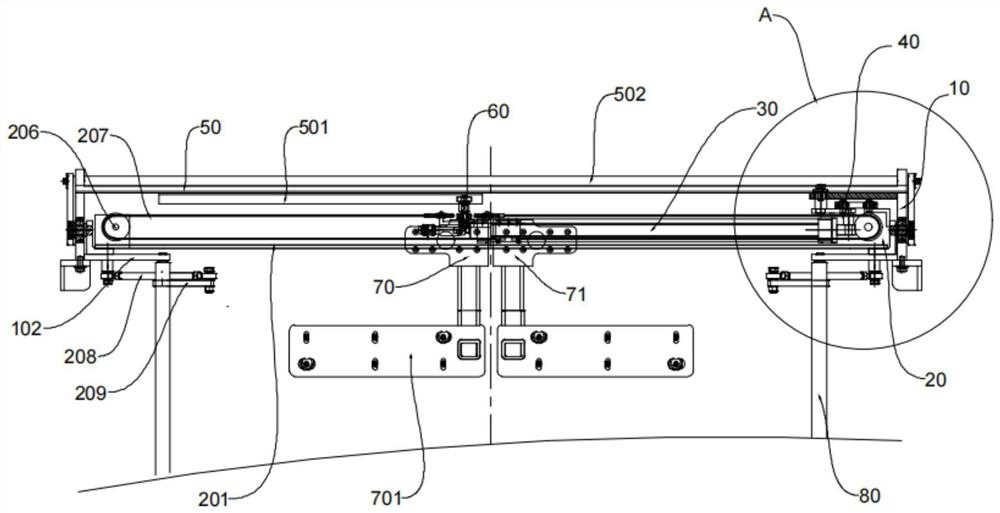
[0029] refer to figure 1 and figure 2 , the embodiment of the present invention provides a driving mechanism movement direction conversion device, including a fixed frame 10, a movable frame 20 and a power source 30, a guide wheel 60 is installed on the movable frame 20, a guide rail 501 is installed on the fixed frame 10, and the power source 30 can drive the guide wheel 60 to move in the guide rail 501. A link mechanism 40 is connected between the tailstock 301 of the power source and the movable frame 20. When the guide wheel 60 passes through the curve of the guide rail 501, the link mechanism 40 can drive the movable frame. 20 moves on the fixed frame 10, and the movable frame 20 can drive the guide wheel 60 to move longitudinally in the guide rail 501 relative to the straight part of the guide rail. That is, the link mechanism 40 drives the movable frame 20 to move on the fixed frame 10 through the reaction force of the power source 30 when the guide wheel 60 passes th...

Embodiment 2

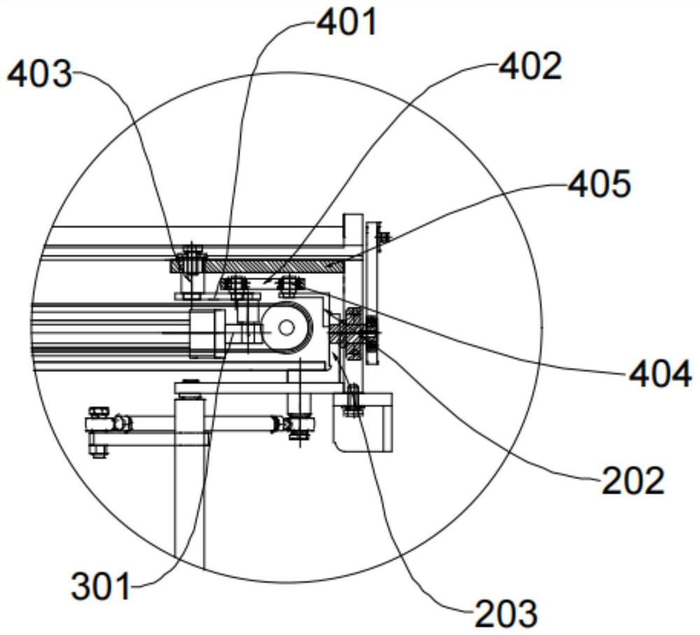
[0032] refer to figure 1 and figure 2, the embodiment of the present invention provides a driving mechanism movement direction conversion device, on the basis of the first embodiment, wherein, the two ends of the movable frame 20 are installed on the fixed frame 10, and the fixed frame 10 is provided with a fixed tray 50, a guide rail 501 Located under the fixed tray 50, the link mechanism 40 includes a first link 401 and a second link 402, the two ends of the first link 401 rotate respectively to connect the tailstock 301 of the power source and the fixed tray 50, and the second link 402 The two ends rotate respectively to connect the first connecting rod 401 and the movable frame 20, and the tailstock 301 of the power source reacts to drive the first connecting rod 401 and the second connecting rod 402 to form a movable lever. , the steering force reaches its maximum. Let the connecting point between the first connecting rod 401 and the second connecting rod 402 be a leve...

Embodiment 3

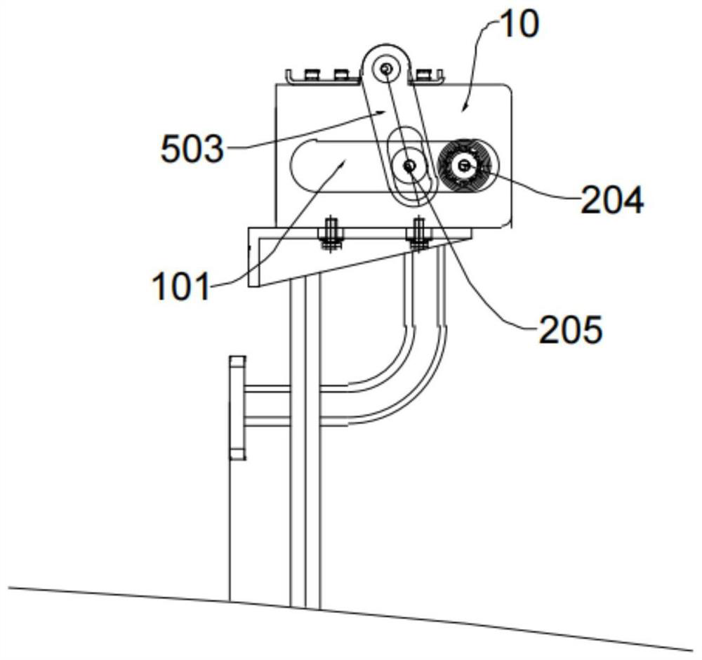
[0037] The embodiment of the present invention provides a device for changing the direction of motion of the drive mechanism. On the basis of Embodiment 1, refer to image 3 , wherein, the fixed frame 10 is provided with a bearing groove 101, and the two ends of the movable frame 20 are respectively provided with a driving bearing 204 and a driven bearing 205, and the driving bearing 204 and the driven bearing 205 are all movably installed in the bearing groove 101, and the driven bearing 205 and the fixed tray 50 are connected with a synchronous swing arm 503, and a synchronous lever 502 is connected between the synchronous swing arms 503 on both sides. Movement in the bearing groove 101, at the same time, because the driven bearing 205 is connected with the synchronous lever 502 through the synchronous swing arm 503, the movable frames 20 on both sides are synchronously oscillated to carry out longitudinal movement.


PUM


Abstract

The invention discloses a driving mechanism motion direction conversion device and method. The driving mechanism motion direction conversion device comprises a fixed frame, a movable frame and a power source; a guide wheel is mounted on the movable frame; a guide rail is mounted on the fixed frame; the power source can drive the guide wheel to move in the guide rail; a connecting rod mechanism is connected between a tailstock of the power source and the movable frame; and when the guide wheel passes through a guide rail bend, the connecting rod mechanism can drive the movable frame to move on the fixed frame, and the movable frame can drive the guide wheel to longitudinally move in the guide rail relative to the linear part of the guide rail. According to the driving mechanism motion direction conversion device and method, conversion of the motion direction of a driving mechanism is achieved, vertical plugging and pulling can be conducted, and the problems caused by the fact that the power source is directly fixed to the movable frame are solved.

Description

technical field [0001] The invention relates to the field of drive equipment, in particular to a device and method for converting the motion direction of a drive mechanism. Background technique [0002] At present, the general power source can only drive the object to move in a straight line along the axis of the power source, but when the object encounters an inflection point when moving in a straight line, there will be a problem of changing direction. The traditional method is that the tailstock of the power source is fixedly connected with the movable frame, and then Utilizing the power source and the extrusion of the curved part of the track at the front end of the drive, the reaction force is decomposed and acts on the guide wheels and sliders on the movable frame to drive the movable frame to move longitudinally relative to the fixed frame, that is, the guide wheels and sliders at this time On the one hand, it moves laterally relative to the movable frame, and also mo...

Claims


Application Information

Patent Timeline
Patent Type & Authority Applications(China)
IPC IPC(8): E05F15/53E05D13/00E05D15/02E05F15/63
CPCE05F15/53E05D13/00E05D15/02E05F15/63Y02T10/70
Inventor 朱有进
Owner 金湖县金宇客车门泵厂
Why Eureka
Try Eureka