
Automatic hydrostatic test device for boiler tube panel and working method of automatic hydrostatic test device

A hydrostatic test and automatic water supply technology, which is applied to measuring devices, cleaning methods and appliances, chemical instruments and methods, etc., can solve the problems of high pressure of boiler tube panel hydrostatic test, hidden dangers of manual operation, and insufficient plugging. Reliability and other issues, to achieve efficient hydraulic test inspection, save manpower and material resources, and eliminate potential safety hazards

Pending Publication Date: 2021-09-21
XIAN THERMAL POWER RES INST CO LTD
View PDF0 Cites 0 Cited by
  • Summary
  • Abstract
  • Description
  • Claims
  • Application Information

AI Technical Summary

Problems solved by technology

[0003] At present, the water pressure test method of the boiler tube panel is manually operated. One operator is responsible for water supply, one operator is responsible for blocking the tube, and one operator is responsible for the operation of the pressure test pump and checking whether there is leakage in the tube panel. After the test, it is necessary to remove the accumulated water in the tube panel, which is time-consuming and labor-intensive. Moreover, due to the high pressure of the boiler tube panel hydrostatic test, there may be occasions when the plug is not securely sealed and flies out, and there is a great safety hazard in manual operation. , and inefficient

Method used


Image

  • Automatic hydrostatic test device for boiler tube panel and working method of automatic hydrostatic test device
  • Automatic hydrostatic test device for boiler tube panel and working method of automatic hydrostatic test device

Examples


Embodiment Construction

[0030] The present invention will be described in further detail below in conjunction with accompanying drawing, and its content is explanation of the present invention rather than limitation:

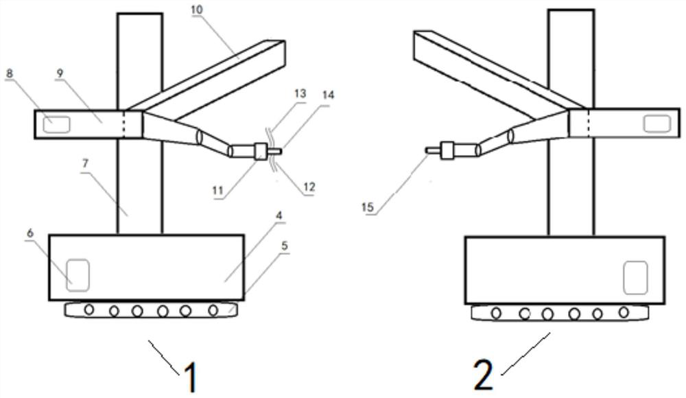
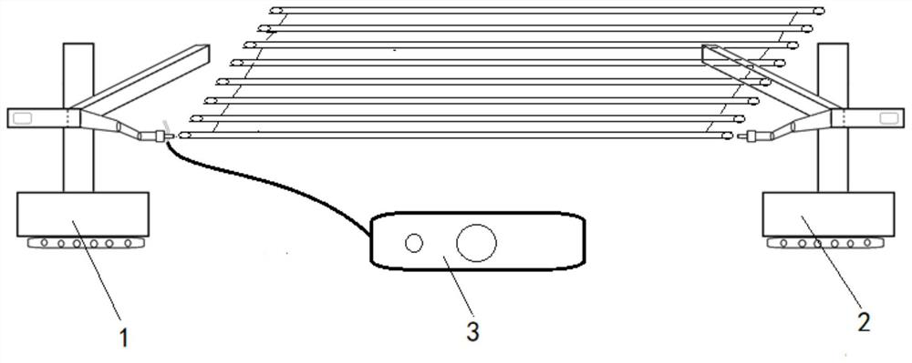
[0031] Such as figure 1 , is boiler tube screen automatic water pressure testing device of the present invention, comprises automatic water supply machine 1, automatic sealing machine 2 and electric pressure test pump 3; Automatic water supply machine 1 and automatic sealing machine 2 all comprise base 4, power Device 5, movable support assembly, mechanical arm 9, nozzle tracking and positioning device 11 and power module 6; The bracket assembly is movably connected with the mechanical arm 9, and the nozzle tracking and positioning device 11 is arranged on the mechanical arm 9; the structure and connection relationship of this part are the same.

[0032] The difference is that the mechanical arm 9 of the automatic water filling machine 1 is connected with a water supply tool 14, and t...


PUM


Abstract

The invention discloses an automatic hydrostatic test device for a boiler tube panel and a working method of the automatic hydrostatic test device, belonging to the technical field of detection devices. The automatic hydrostatic test device comprises an automatic water feeder, an automatic plugging machine and an electric pressure test pump, wherein each of the automatic water feeder and the automatic plugging machine each comprises a base, a power device, a movable support assembly, a mechanical arm, a pipe opening tracking and positioning device and a power module, the power module is arranged on the base, the lower portion of the base is connected with the power device, the upper portion of the base is connected with the movable support assembly, the movable support assembly is movably connected with the mechanical arm, and the pipe opening tracking and positioning device is arranged on the mechanical arm; the mechanical arm of the automatic water feeder is connected with a water feeding tool, and the water feeding tool is connected with the electric pressure test pump and a compressed air system; and a mechanical arm of the automatic plugging machine is connected with a plugging tool. The device is reasonable in design, high in automation degree and capable of efficiently achieving hydraulic pressure test inspection of batch pipe fittings, improves efficiency, saves manpower and material resources and eliminates potential safety hazards possibly existing.

Description

technical field [0001] The invention belongs to the technical field of detection devices, and in particular relates to a boiler tube panel automatic hydraulic pressure test device and a working method thereof. Background technique [0002] Boiler equipment tube panels include water-cooled walls and serpentine tubes. According to standard requirements, the above-mentioned components need to undergo hydrostatic tests after they are manufactured to assess their strength and expose possible defects in the manufacturing process. [0003] At present, the water pressure test method of the boiler tube panel is manually operated. One operator is responsible for water supply, one operator is responsible for blocking the tube, and one operator is responsible for the operation of the pressure test pump and checking whether there is leakage in the tube panel. After the test, it is necessary to remove the accumulated water in the tube panel, which is time-consuming and labor-intensive. Mo...

Claims


Application Information

Patent Timeline
Patent Type & Authority Applications(China)
IPC IPC(8): G01N3/12G01N3/02G01M3/02B08B9/032
CPCG01N3/12G01N3/02G01M3/02B08B9/0328G01N2203/0003G01N2203/0019G01N2203/0048G01N2203/006G01N2203/0274
Inventor 刘响亮胡新元任宁博鲁刚刘朝曹剑峰李太江杨百勋
Owner XIAN THERMAL POWER RES INST CO LTD
Learn More