Shunt type current measurement compensation method and device

A technology of current measurement and compensation method, which is applied in the direction of measuring devices, only measuring current, measuring electrical variables, etc. It can solve the problem that the look-up table method cannot compensate for the influence of self-heating measurement in real time, the error of the shunt, and the ambient temperature does not represent the shunt, etc. question

Active Publication Date: 2021-09-21
睿控智行汽车技术南通有限公司
View PDF7 Cites 3 Cited by
  • Summary
  • Abstract
  • Description
  • Claims
  • Application Information

AI Technical Summary

Problems solved by technology

[0006] The disadvantage of the current method of looking up table compensation through the ambient temperature is that the ambient temperature does not represent the temperature of the shunt itself, and the temperature change has a certain hysteresis. The self-heating of the shunt itself will also cause errors. The look-up table method cannot compensate for the measurement impact caused by self-heating in real time

Method used


Image

  • Shunt type current measurement compensation method and device
  • Shunt type current measurement compensation method and device
  • Shunt type current measurement compensation method and device

Examples


Embodiment 1

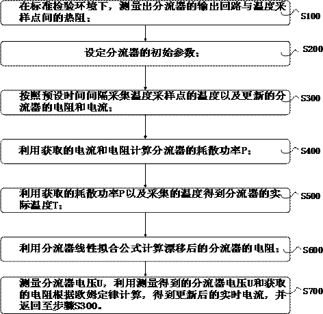
[0066] figure 1 A shunt-type current measurement compensation method is provided for an embodiment of the present invention, comprising the following steps:

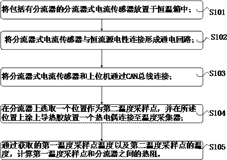
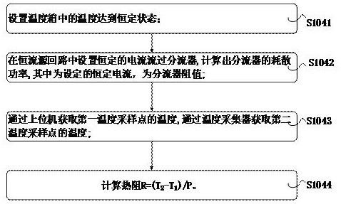
[0067] S100. Under the standard inspection environment, measure the thermal resistance R between the output circuit of the shunt and the first temperature sampling point th ;

[0068] S200. Set the initial parameters of the shunt, the initial parameters specifically include the temperature coefficient k of the shunt,

[0069] shunt at T 0 Resistance at temperature R 0 , the thermal resistance R between the shunt body and the temperature sampling point th Wait;

[0070] S300. Collect the temperature T of the first temperature sampling point according to the preset time interval a and updated points

[0071] The resistance and current of the flowmeter, thereby sampling the temperature, resistance and current through the set preset time interval;

[0072] S400. Calculate the power dissipation P of the shunt by using...

Embodiment 2

[0097] Figure 5 An embodiment of the present invention provides a shunt type current measurement and compensation device, including:

[0098] The measurement module is used to measure the thermal resistance R between the output circuit of the shunt on the PCB circuit board and the first temperature sampling point th , and transmitted to the data acquisition module; the initialization module 1 is used to set the initial parameters of the shunt; the data acquisition module 3 is used to collect the temperature T of the first temperature sampling point according to the preset time interval a And the resistance and current of the updated shunt; the first data calculation module 4 is used to calculate the dissipated power P of the shunt according to the obtained current and resistance; the second data calculation module 5 is used to calculate the dissipated power P according to the obtained multiplied by the thermal resistance R th Get the temperature difference, that is, the tem...


PUM


Abstract

The invention discloses a shunt type current measurement compensation method, which comprises the following steps of: measuring thermal resistance Rth between an output loop of a shunt and a first temperature sampling point in a standard inspection environment; setting initial parameters of the diverter; collecting the temperature Ta of the first temperature sampling point and the updated resistance and current of the shunt according to a preset time interval; calculating the dissipation power P of the shunt by using the obtained current and resistance; obtaining the actual temperature T of the diverter through the obtained dissipation power P and the collected temperature Ta; calculating the resistance of the diverter after drifting by using a linear fitting formula of the diverter; and measuring the voltage U of the shunt, and calculating by using the measured voltage U of the shunt and the obtained resistance according to the Ohm law to obtain the updated real-time current. According to the invention, the current at the next moment is compensated by using the current at the previous moment, the process is repeated, the influence of the current on the current measurement is reduced, and the current measurement precision is improved.

Description

technical field [0001] The invention relates to the technical field of automobile shunts, in particular to a shunt-type current measurement and compensation method and device. Background technique [0002] At present, the shunt type current sensor for electric vehicles is mainly composed of a power supply module, CAN communication, MCU, ADC analog-to-digital conversion, and a shunt. In an ideal state, the voltage difference generated when the current flows through the shunt is collected by the ADC, and the current value at that time is calculated inside the MCU, but the shunt has a thermal temperature coefficient of resistance, and the resistance will have a certain drift at different temperatures. The offset of the resistance value can be expressed by the following formula: [0003] R=R 0 +K(T-T 0 ) [0004] R 0 is the initial resistance, k is the temperature coefficient, T 0 is the initial temperature. [0005] At present, in order to compensate for the error caused...

Claims


Application Information

Patent Timeline
Patent Type & Authority Applications(China)
IPC IPC(8): G01R19/00G06F17/10
CPCG01R19/0092G06F17/10
Inventor 高挺
Owner 睿控智行汽车技术南通有限公司
Why Eureka
Try Eureka