Control method for improving aerodynamic stability of shipboard aircraft engine during takeoff

A control method and engine technology, applied in the direction of non-electric variable control, temperature control, control/regulation system, etc., can solve the problems that it is difficult to ensure the stability of the take-off state and thrust demand of carrier-based aircraft at the same time, so as to improve the working stability, Guaranteed thrust effect

Active Publication Date: 2021-09-21
AECC SHENYANG ENGINE RES INST
View PDF5 Cites 3 Cited by
  • Summary
  • Abstract
  • Description
  • Claims
  • Application Information

AI Technical Summary

Problems solved by technology

[0006] The purpose of this application is to provide a control method for improving the aerodynamic stability of the carrier-based aircraft engine when it takes off, so as to solve the problem that it is difficult to simultaneously ensure the stability and thrust demand of the carrier-based aircraft in the take-off state in the prior art

Method used


Image

  • Control method for improving aerodynamic stability of shipboard aircraft engine during takeoff
  • Control method for improving aerodynamic stability of shipboard aircraft engine during takeoff
  • Control method for improving aerodynamic stability of shipboard aircraft engine during takeoff

Examples


Embodiment 1

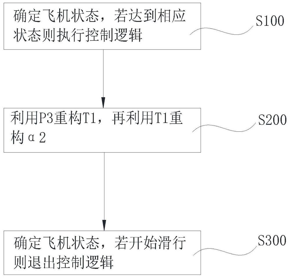
[0046] Embodiment 1, a control method for improving the aerodynamic stability of a carrier-based aircraft engine during take-off, such as figure 1 shown, including,

[0047] Step S100, determine whether the aircraft is on the ground or the fuel oil reaches the maximum state, if so, execute T 1 Refactor the control logic, otherwise do not execute;

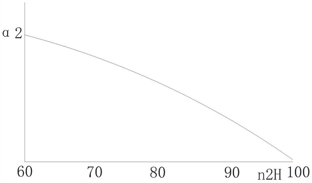
[0048] Step S200, using the engine outlet total pressure P 3 Total inlet temperature T of reconstructed engine 1 , using the reconstructed engine inlet total temperature T 1 Obtain the speed, temperature, afterburner oil, and nozzle control plan values ​​at the maximum state of the engine, and use the reconstructed engine inlet total temperature T 1 Recalculate the relative conversion speed n of the high pressure rotor 2R , use the relative conversion speed n of the high temperature rotor 2R Get the compressor adjustable blade angle α 2 Control plan value to control carrier aircraft;

[0049] Step S300, determine the state o...

Embodiment 2

[0101] Embodiment 2, as a specific implementation, a control system for improving the aerodynamic stability of a carrier-based aircraft engine during take-off, such as Figure 13 As shown, it includes a control logic confirmation module 5 , a control logic execution module 6 , and a control logic exit module 7 .

[0102] The control logic confirmation module 5 is used to determine the state of the aircraft, and when the aircraft is on the ground and the fuel oil reaches the maximum state, execute T 1 Refactoring control logic;

[0103] The control logic execution module 6 is used to utilize the engine outlet total pressure P 3 Total inlet temperature T of reconstructed engine 1 , using the reconstructed engine inlet total temperature T 1 Obtain the speed, temperature, afterburner oil, and nozzle control plan values ​​at the maximum state of the engine, and use the reconstructed engine inlet total temperature T 1 Recalculate the relative conversion speed n of the high press...

Embodiment 3

[0123] Embodiment 3, as a specific implementation, also includes a carrier-based aircraft engine, which includes the control system as described in Embodiment 2. The scheme adopted in the prior art does not consider the thrust of the engine, but uses this system to control The engine can not only ensure the working stability of the engine, but also take into account the performance of the engine thrust during take-off.


PUM


Abstract

The invention relates to the field of shipboard aircraft engine design, in particular to a control method for improving aerodynamic stability of a shipboard aircraft engine during takeoff, which comprises the following steps of: determining whether an aircraft is on the ground and thrust augmentation oil reaches a maximum state, and if so, executing control logic on the aircraft; using the engine outlet total pressure for reconstructing the engine inlet total temperature, using the reconstructed engine inlet total temperature for obtaining the rotating speed, the temperature, the thrust augmentation oil and the nozzle control plan value of the engine in the maximum state, and using the reconstructed engine inlet total temperature for obtaining the relative conversion rotating speed of a high-pressure rotor; using the relative conversion rotating speed of the high-temperature rotor for obtaining the angle control plan value of the adjustable blade of the gas compressor, and controlling the shipboard aircraft; and determining the state of the aircraft, and if the aircraft starts to slide forwards, quitting the aircraft control logic. The method has the technical effect of simultaneously ensuring the stability of the take-off state of the shipboard aircraft and the thrust demand.

Description

technical field [0001] The application belongs to the field of carrier aircraft engine design, and in particular relates to a control method for improving the aerodynamic stability of a carrier aircraft engine when it takes off. Background technique [0002] When a carrier-based aircraft takes off or conducts an engine test run on the ship, the tail nozzle ejects high-speed, high-temperature gas, which will affect the personnel and equipment in the nearby area. Therefore, a deflector is provided on the deck of the aircraft carrier to change the direction of the gas to protect personnel and equipment. But this also brings new problems: the deflector will reflect the high-temperature gas to the inlet of the aircraft inlet, forming a total temperature distortion and reducing the engine surge margin. Especially when the aircraft is taking off, the engine is in a state of full afterburner, the temperature of the gas reflected by the deflector is high, the total temperature of th...

Claims


Application Information

Patent Timeline
Patent Type & Authority Applications(China)
IPC IPC(8): G05D23/20
CPCG05D23/20
Inventor 韩文俊郭海红邢洋李兆红刘亚君唐兰
Owner AECC SHENYANG ENGINE RES INST
Why Eureka
Try Eureka