
Waste gas recovery device for lubricating oil production and use method thereof

A waste gas recovery and lubricating oil technology, which is applied in drinking water devices, combined devices, water supply devices, etc., can solve the problems of manual water addition, increase the burden on staff, and high water consumption, so as to save water, improve resource utilization, and spray water. The effect of reducing the amount of water

Inactive Publication Date: 2021-09-24
山东陆邦石化有限公司
View PDF0 Cites 1 Cited by
  • Summary
  • Abstract
  • Description
  • Claims
  • Application Information

AI Technical Summary

Problems solved by technology

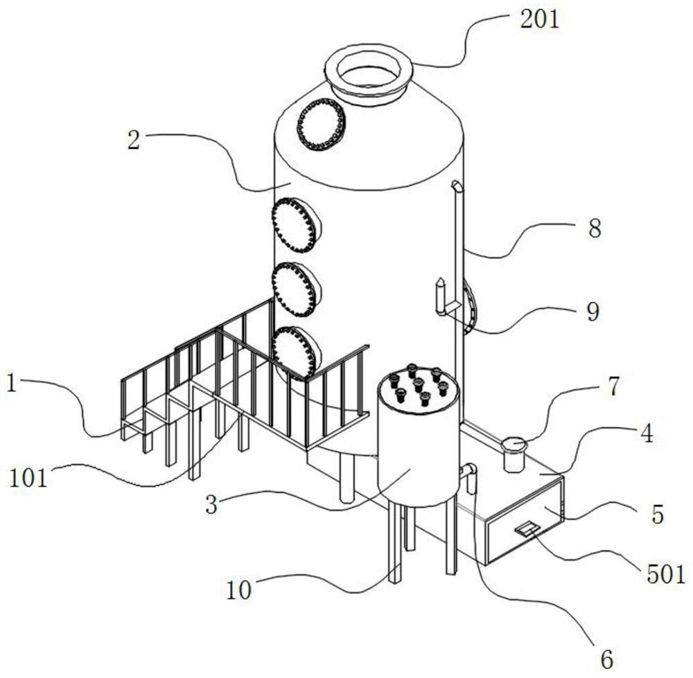
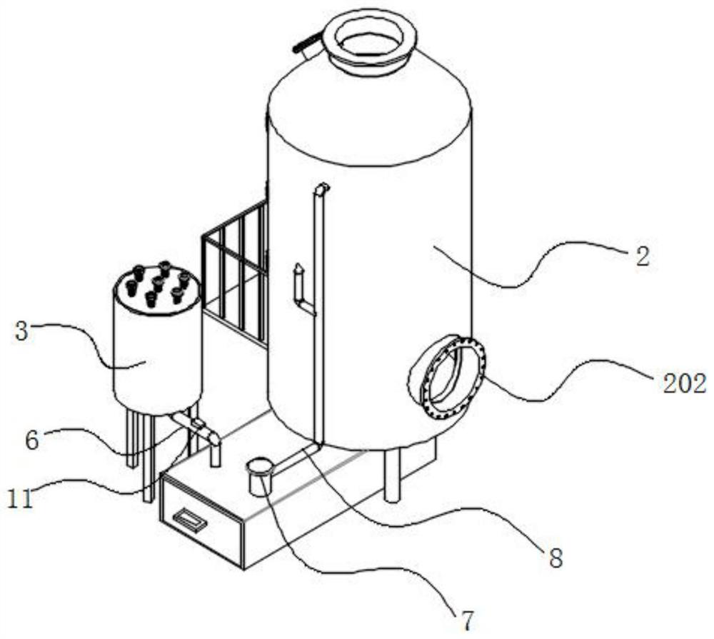
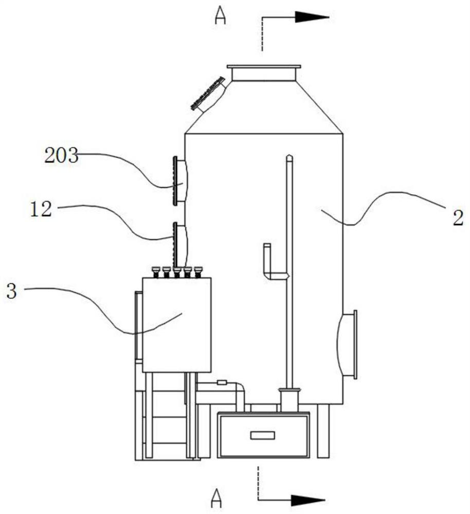
[0005] The purpose of the present invention is to provide a waste gas recovery device for lubricating oil production and its use method, to solve the problem that the existing spray towers consume more water when spraying water, which is not conducive to saving water, and with the waste gas belt Part of the water mist comes out, and the water spray system of the spray tower needs to add water in time, and some even need to add water manually, which increases the burden on the staff

Method used


Image

  • Waste gas recovery device for lubricating oil production and use method thereof
  • Waste gas recovery device for lubricating oil production and use method thereof
  • Waste gas recovery device for lubricating oil production and use method thereof

Examples


Embodiment Construction

[0033] The following will clearly and completely describe the technical solutions in the embodiments of the present invention with reference to the accompanying drawings in the embodiments of the present invention. Obviously, the described embodiments are only some, not all, embodiments of the present invention. Based on the embodiments of the present invention, all other embodiments obtained by persons of ordinary skill in the art without creative efforts fall within the protection scope of the present invention.

[0034] In the description of the present invention, it should be understood that the terms "upper", "middle", "outer", "inner" and "surrounding" orientation or positional relationship are only for the convenience of describing the present invention and simplifying the description, rather than Any indication or implication that a referenced component or element must have a particular orientation, be constructed and operate in a particular orientation should not be co...


PUM


Abstract

The invention discloses a waste gas recovery device for lubricating oil production and a use method thereof, and relates to the technical field of waste gas treatment. The device comprises stairs, a spraying tower and a water collecting tower, an exhaust port is formed in the upper end of the spraying tower, air inlets are formed in the peripheral side face of the spraying tower, a demister, an upper transition pipe and a lower transition pipe are arranged in the spraying tower, the demister is located at the top of the spraying tower, the upper transition pipe is located on the lower side of the demister, and the lower transition pipe is located on the lower side of the upper transition pipe. The upper transition pipe and the lower transition pipe are communicated with a plurality of nozzles. By using the water collecting cylinder, the device can collect and store rainwater and then supply water to a spraying system of the spraying tower, compared with a traditional device, the device is more efficient, and the resource utilization rate is increased; and according to the invention, the separation plate is used, and the herringbone separation holes can be used for blocking part of waste gas impurities, so that the content of impurities in waste gas is reduced during subsequent water spraying, the water spraying amount of the nozzle can be correspondingly reduced, the effect of saving water is achieved, and the device is more environment-friendly.

Description

technical field [0001] The invention belongs to the technical field of waste gas treatment, and in particular relates to a waste gas recovery device used for lubricating oil production and a use method thereof. Background technique [0002] Lubricating oil is a liquid or semi-solid lubricant used in various types of automobiles and mechanical equipment to reduce friction and protect machinery and processed parts. It mainly plays the roles of lubrication, auxiliary cooling, rust prevention, cleaning, sealing and buffering. The production process of lubricating oil will also produce a large amount of waste gas, which needs to be recycled before it can be discharged into the atmosphere to reduce pollution. [0003] Existing waste gas treatment devices are generally equipped with a spray tower structure to pretreat the waste gas. After the waste gas enters the spray tower, water will be sprayed to reduce dust first, so that the large impurities in the waste gas will fall and mix...

Claims


Application Information

Patent Timeline
Patent Type & Authority Applications(China)
IPC IPC(8): B01D50/00B01D35/027B01D29/58B01D29/01E03F5/10E03B3/02
CPCB01D35/027B01D29/58B01D29/01E03F5/10E03B3/02Y02A20/108
Inventor 宗文学
Owner 山东陆邦石化有限公司
Learn More