
Fine drilling equipment for hardware production

A technology of drilling equipment and hardware, which is applied in the field of hardware, can solve the problems of increasing labor force, manual operation, etc., and achieve the effects of reducing labor force, preventing drilling failure, and strong practicability

Inactive Publication Date: 2021-09-24
顾述翠
View PDF0 Cites 1 Cited by
  • Summary
  • Abstract
  • Description
  • Claims
  • Application Information

AI Technical Summary

Problems solved by technology

[0003] The purpose of the present invention is to provide a kind of drilling equipment for hardware production, to solve the problem that the drilling equipment in the prior art is mostly carried out manually, which increases the labor force.

Method used


Image

  • Fine drilling equipment for hardware production
  • Fine drilling equipment for hardware production
  • Fine drilling equipment for hardware production

Examples


Embodiment 1

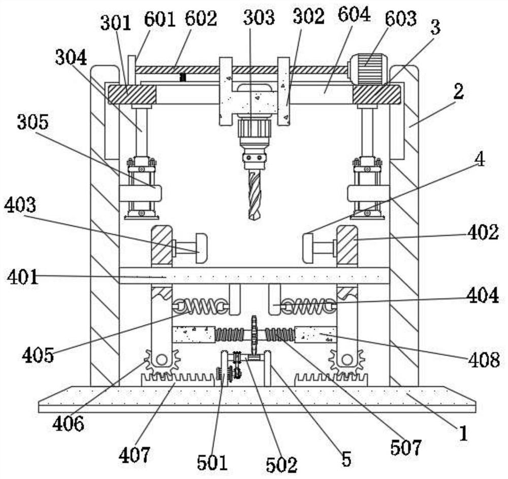
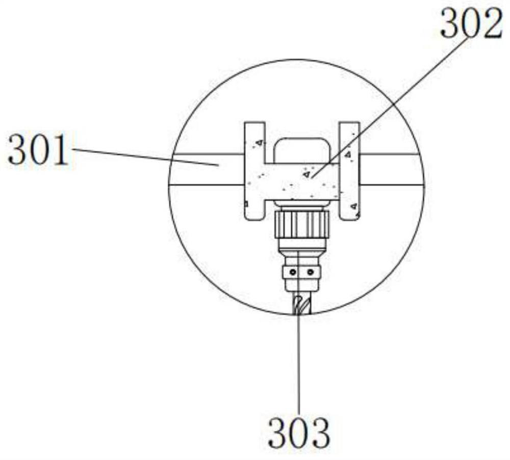
[0040] see figure 1 , 7 -10, the present invention provides a technical solution: a fine drilling equipment for hardware production, including a base 1 and a first vertical plate 2, the left and right sides of the upper surface of the base 1 are fixed with the first vertical plate 2, The upper inner side of the first vertical plate 2 is processed with a chute, the upper inner side of the first vertical plate 2 is equipped with a drilling device 3, and the drilling device 3 includes a first horizontal plate 301, an H-shaped plate 302, and the first horizontal plate 301 The outer wall of the outer side fits with the inner wall of the chute of the first vertical plate 2 in a gap, the first vertical plate 2 can limit the position of the first horizontal plate 301 through the chute, and the middle part of the first horizontal plate 301 is movably connected with an H-shaped plate 302 , the upper end of the first horizontal plate 301 is provided with a moving device, the moving devi...

Embodiment 2

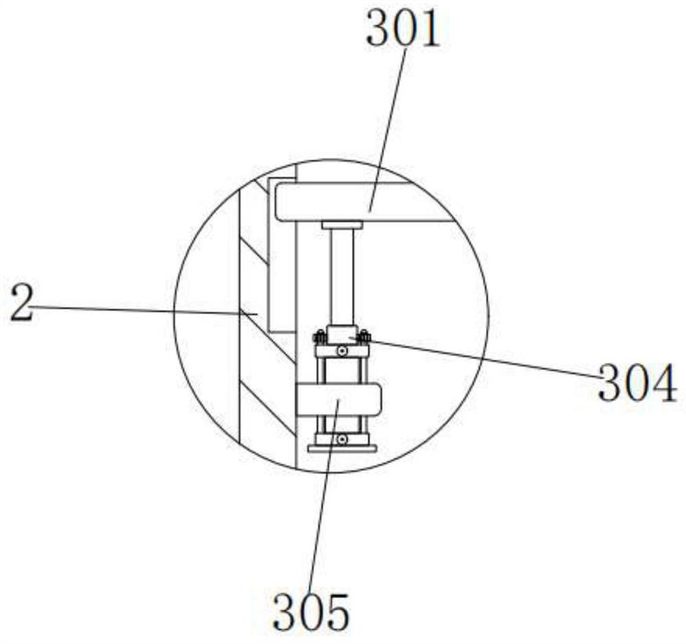
[0044] see Figure 1-6 As shown, on the basis of Embodiment 1, the drilling device 3 also includes a drilling machine 303, a hydraulic cylinder 304, and a second horizontal plate 305, and a drilling machine 303 is fixedly attached to the inside of the H-shaped plate 302. , the model of the drilling machine 303 is DW1-120D, the left and right sides of the drilling machine 303 are provided with a hydraulic cylinder 304, the model of the hydraulic cylinder 304 is MOB, the upper outer wall of the hydraulic cylinder 304 and the lower surface outer wall of the first horizontal plate 301 Fixedly connected, the hydraulic cylinder 304 can drive the drilling machine 303 to move through the first horizontal plate 301, etc., the second horizontal plate 305 is arranged below the first horizontal plate 301, and the inside of the second horizontal plate 305 is fixed to the outer wall of the hydraulic cylinder 304 connected, the outer outer walls of the left and right second horizontal plates...


PUM


Abstract

The invention discloses fine drilling equipment for hardware production, which comprises a base and a first vertical plate; a sliding groove is machined in the upper portion of the inner side of the first vertical plate; a drilling device is installed on the upper portion of the inner side of the first vertical plate; the drilling device comprises a first transverse plate and an H-shaped plate; a moving device is arranged at the upper end of the first transverse plate; and the moving device comprises a base plate, a threaded shaft, a moving motor, a through groove, a strip-shaped graduated scale and a first pointer. According to the drilling equipment for hardware production, the moving motor is started, the moving motor drives the threaded shaft to rotate and drives the H-shaped plate to move in the through groove; the position, pointed by the first pointer, of the strip-shaped graduated scale is observed; when the specified distance is reached, the moving motor is stopped; then, punching is carried out; punching of different positions of hardware can be met; the practicability is high; furthermore, deviation is avoided through cooperation of the strip-shaped graduated scale; drilling is refined, and punching failure is prevented.

Description

technical field [0001] The invention belongs to the technical field of hardware, and in particular relates to a fine drilling device for hardware production. Background technique [0002] Hardware refers to the tools obtained by processing and casting gold, silver, copper, iron, tin and other metals, which are used to fix things, process things, decorate, etc. Hardware can be seen everywhere in life. Hardware is inseparable. For example, some hardware needs to have holes, which requires drilling equipment to punch holes in the hardware. However, most of the drilling equipment in the prior art is manually performed, which increases the labor force. And the drilling position is fixed, the scope of application is small, and the drilling is not fine, which will easily lead to deviations in the drilling position of the hardware. Contents of the invention [0003] The purpose of the present invention is to provide a kind of drilling equipment for hardware production, to solve t...

Claims


Application Information

Patent Timeline
Patent Type & Authority Applications(China)
IPC IPC(8): B23B47/22B23Q3/06B23Q15/22
CPCB23Q15/22B23Q3/06B23Q5/26
Inventor 顾述翠
Owner 顾述翠
Learn More