A multi-machine workpiece clamping device capable of removing iron scraps for combined machining
A clamping device and combined processing technology, which is applied to metal processing machinery parts, positioning devices, metal processing equipment, etc.
- Summary
- Abstract
- Description
- Claims
- Application Information
AI Technical Summary
Problems solved by technology
Method used
Image

Examples
Embodiment 1
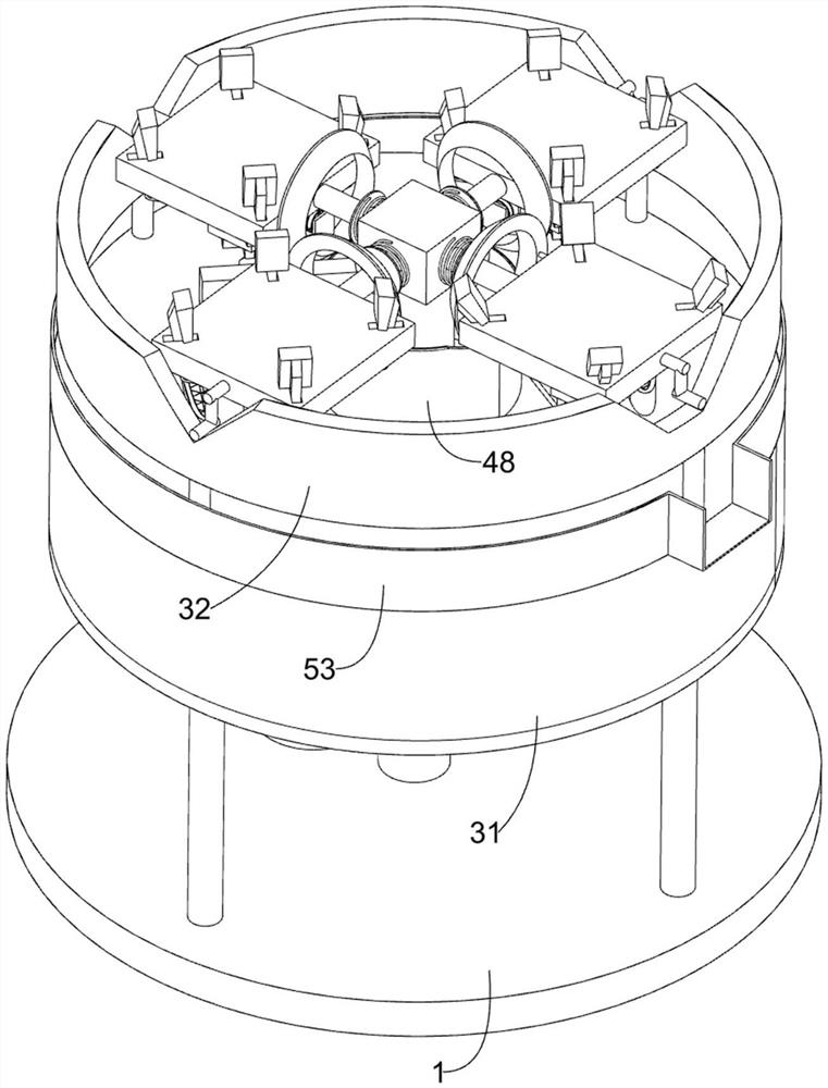
[0026] A multi-machine workpiece clamping device that can remove iron scraps for combined machining, such as Figure 1-6 As shown, it includes a supporting chassis 1, a rotating assembly 2, an overturning assembly 3 and a clamping device 4. The rotating assembly 2 is fixedly installed on the supporting chassis 1, and the top surface of the supporting chassis 1 is provided with a The turning assembly 3 and the clamping device 4 for clamping the workpiece are arranged on the rotating assembly 2 .
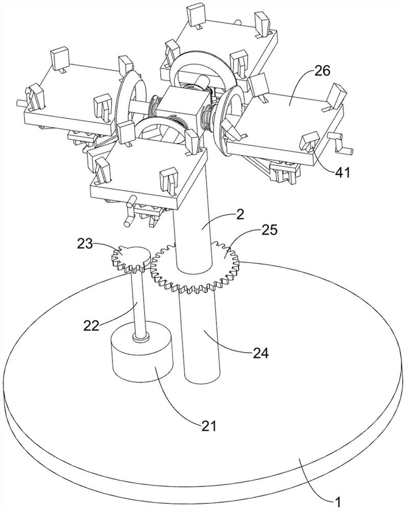
[0027] The rotating assembly 2 includes a motor 21, a rotating shaft 22, a missing gear 23, a turret 24, a spur gear 25, and a placing frame 26. A motor 21 is fixedly installed on the top surface of the supporting chassis 1, and a rotating shaft 22 is welded on the output shaft of the motor 21. , the top of the rotating shaft 22 away from the motor 21 is fixedly connected with a missing gear 23, the supporting chassis 1 is rotatably connected with a turret 24, and the turret 24 is fix...
Embodiment 2
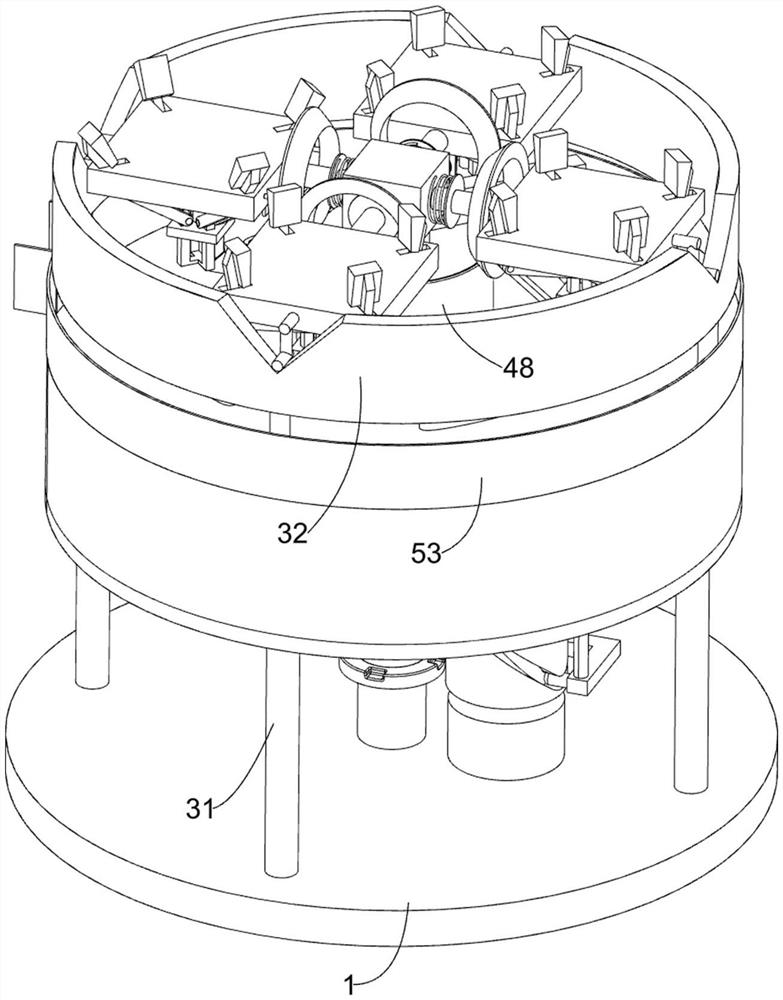
[0034] On the basis of Example 1, as Figure 7-8 As shown, it also includes an auxiliary component 5 for removing iron filings, and the supporting frame 31 is provided with an auxiliary component 5 for removing iron filings. 521. The guide groove plate 53 and the air outlet pipe 54 with the sieve plate are provided with a slotted cylinder 51 on the rotating shaft 22, and the push ring 52 is connected to the support frame 31 in a liftable manner. The gas in the support frame 31 is squeezed, and the bottom surface of the push ring 52 is provided with a second clamping column frame 521, and the second clamping column frame 521 is limitedly matched with the slotted cylinder 51, and the slotted cylinder 51 is used to push the second column clamping frame 521. The clamping column frame 521 and the push ring 52 reciprocate up and down. The guide groove plate 53 is fixedly installed on the support frame 31. The support frame 31 is provided with two pairs of air outlet pipes 54 with si...
Embodiment 3
[0037] On the basis of Example 2, as Figure 7-8 As shown, an anti-deviation assembly 6 is also included. The anti-deviation assembly 6 is arranged on the turret 24. The anti-deviation assembly 6 is used to prevent the turret 24 and its upper device from being deflected. The anti-deviation assembly 6 includes a slot. The ring 61 and the limit frame 62, the turret 24 is welded with a slotted ring 61, the limit frame 62 is arranged on the second clamping frame 521, and at least a part of the limit frame 62 is arranged in the groove of the slotted ring 61, and the limit The spacer 62 is used to hold the slotted ring 61 .
[0038] When the second column clamping frame 521 moves upward, the second clamping column frame 521 will drive the limiting frame 62 to move upward, and the limiting frame 62 will no longer clamp the slotted ring 61, so that the turret 24 and its upper device can rotate. After the position of the workpiece is switched, when the workpiece is being processed, th...
PUM
 Abstract
Description
Claims
Application Information
 - R&D
- Intellectual Property
- Life Sciences
- Materials
- Tech Scout
- Unparalleled Data Quality
- Higher Quality Content
- 60% Fewer Hallucinations
Browse by: Latest US Patents, China's latest patents, Technical Efficacy Thesaurus, Application Domain, Technology Topic, Popular Technical Reports.
© 2025 PatSnap. All rights reserved.Legal|Privacy policy|Modern Slavery Act Transparency Statement|Sitemap|About US| Contact US: help@patsnap.com