Al technical title is built by PatSnap Al team. It summarizes the technical point description of the patent document.
A molding equipment and technology of silica gel, which is applied in the field of molding equipment and molding technology of silica gel sleeves, can solve the problems that the distance between two rollers cannot be adjusted, the fluidity of silica gel is too large, and the weight of silica gel is different, so as to shorten the preparation time for feeding, Avoid the effect of automatically adjusting the distance between each other
Active Publication Date: 2021-09-24
海南木方科技有限公司
View PDF6 Cites 5 Cited by
Summary
Abstract
Description
Claims
Application Information
AI Technical Summary
This helps you quickly interpret patents by identifying the three key elements:
Problems solved by technology
Method used
Benefits of technology
Problems solved by technology
[0005] The object of the present invention is to provide a molding equipment and molding process of a silicone sleeve, to solve the problem that the present invention proposed in the above-mentioned background technology avoids the existing silicone feeding device, and uses two rotating rollers to rub the silicone raw material, so that The heat of the silica gel itself rises, resulting in the phenomenon of enhanced fluidity of the silica gel, and the distance between the two rollers cannot be adjusted, and eventually all flow to the lower roller, which solves the phenomenon that the external silica gel may fall to the outer end of the feeding roller, resulting in raw materials The problem of pollution and waste; secondly, the fluidity of silica gel is too large, which makes the density inside itself change, and the weight of silica gel with the same thickness may vary, resulting in uneven feeding, which makes the thickness of the silicone tube produced by the extruder vary. There is a problem with poor quality
Method used
Image
Click on the blue label to locate the original text in one second.
Reading with bidirectional positioning of images and text.
Examples
Embodiment Construction
[0032] The following will clearly and completely describe the technical solutions in the embodiments of the present invention with reference to the accompanying drawings in the embodiments of the present invention. Obviously, the described embodiments are only some, not all, embodiments of the present invention. Based on the embodiments of the present invention, all other embodiments obtained by persons of ordinary skill in the art without creative efforts fall within the protection scope of the present invention.
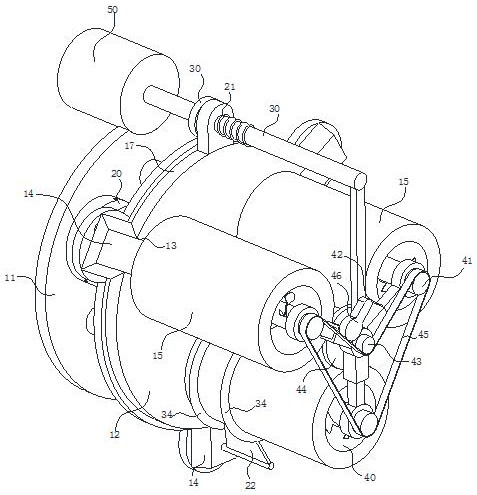
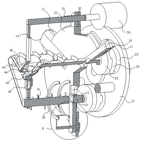
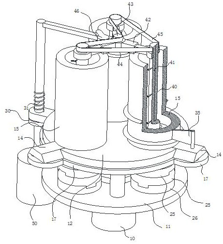
[0033] see Figure 1-8 , the present invention provides a technical solution: a molding equipment for silicone sleeves, including a driving motor 10 and a mounting plate 11, the driving motor 10 is fixedly arranged in the center of the side of the mounting plate 11, and the side wall of the mounting plate 11 is fixedly arranged with a bracket Operating plate 12; the side wall of the operating plate 12 is provided with a radial chute 13 around its axis in an annular...
PUM
Abstract
The invention discloses a silicone rubber sleeve forming device and process and belongs to the technical field of silicone rubber sleeve forming. The silicone rubber sleeve forming device comprises a driving motor and a mounting plate, wherein the driving motor is fixedly arranged in the center of the side edge of the mounting plate, an operation plate is fixedly arranged on the side wall of the mounting plate through a support, radial sliding grooves are formed in the side wall of the operation plate around the axis of the operation plate in an annular array mode, sliding plates are arranged in the sliding grooves in a sliding mode, and rollers used for extruding silicone rubber sleeve raw materials are rotationally arranged on the sliding plates. By the adoption of the silicone rubber sleeve forming device and process, the problems that according to an existing silicone rubber feeding device, two rotating rollers are adopted for rubbing silicone rubber raw materials, so that the heat of silicone rubber rises, the fluidity of the silicone rubber is enhanced, the distance between the two rollers cannot be adjusted, and then the silicone rubber finally flows to the roller at the lower end are solved; and the problem that raw materials are polluted and wasted due to the fact that external silicone rubber possibly falls to the outer ends of the feeding rollers is solved.
Description
technical field [0001] The invention relates to the technical field of molding silicone sleeves, in particular to a molding equipment and a molding process for silicone sleeves. Background technique [0002] With the progress of society, more and more silicone products have entered people's lives, such as silicone tubes, which can be widely used in aviation, electronics, petroleum, chemical, machinery, electrical appliances, medical, oven, food and other industrial sectors. Good electrical insulation sealing, liquid conveying materials, and precision instruments, oil pipelines, household appliances sealing, drinking water pipeline sealing, medicine, etc.; silicone tube is made of silicone rubber raw rubber added to the double-roller rubber mixing machine or closed kneader, Gradually add white carbon black and other additives to refine evenly, and the product is made by extrusion. Silicone tubes are cold and high temperature resistant, harmless, non-toxic and tasteless, and ...
Claims
Application Information
Patent Timeline
Application Date:The date an application was filed.
Publication Date:The date a patent or application was officially published.
First Publication Date:The earliest publication date of a patent with the same application number.
Issue Date:Publication date of the patent grant document.
PCT Entry Date:The Entry date of PCT National Phase.
Estimated Expiry Date:The statutory expiry date of a patent right according to the Patent Law, and it is the longest term of protection that the patent right can achieve without the termination of the patent right due to other reasons(Term extension factor has been taken into account ).
Invalid Date:Actual expiry date is based on effective date or publication date of legal transaction data of invalid patent.