Eureka AIR delivers breakthrough ideas for toughest innovation challenges, trusted by R&D personnel around the world.

Multi-degree-of-freedom grabbing and conveying device for special-shaped component of aviation aircraft landing gear

A technology for special-shaped components and aviation aircraft, applied in the direction of lifting devices, etc., can solve the problems of long distance between work stations, inappropriate setting of external power sources, economic losses, etc.

Active Publication Date: 2021-09-24
黑龙江省机械科学研究院
View PDF10 Cites 0 Cited by
  • Summary
  • Abstract
  • Description
  • Claims
  • Application Information

AI Technical Summary

Problems solved by technology

After maintenance, the components are assembled and tested through multiple processes. There are many maintenance processes, the distance between the stations is long, there are multiple channels to shuttle, and the terrain is complex. It is not suitable to set up an external power source. This is the current situation of most maintenance manufacturers in my country.
After the parts test is completed, the parts need to be assembled in a centralized assembly station. During the assembly process, complex structural parts need to change angles and work steps for precise assembly. After assembly, the landing gear needs to undergo multiple comprehensive experiments. According to the requirements of use, the landing gear is transported to various laboratories and various testing machines are accurately positioned at multiple angles. During the period, manual transfer and positioning are required. The labor intensity of the staff is high, and multiple people are required to work together. For larger and heavier parts, it is very easy to cause labor. damage, inevitably causing economic losses, and even casualties
However, due to the uncertain factors in the human operation process, the positioning time of the aircraft landing gear during assembly and testing varies, which prolongs the positioning time and reduces work efficiency.

Method used


Image

  • Multi-degree-of-freedom grabbing and conveying device for special-shaped component of aviation aircraft landing gear
  • Multi-degree-of-freedom grabbing and conveying device for special-shaped component of aviation aircraft landing gear
  • Multi-degree-of-freedom grabbing and conveying device for special-shaped component of aviation aircraft landing gear

Examples


Embodiment Construction

[0034] It should be noted that, in the case of no conflict, the embodiments of the present invention and the features in the embodiments can be combined with each other.

[0035] The present invention will be described in detail below with reference to the accompanying drawings and examples.

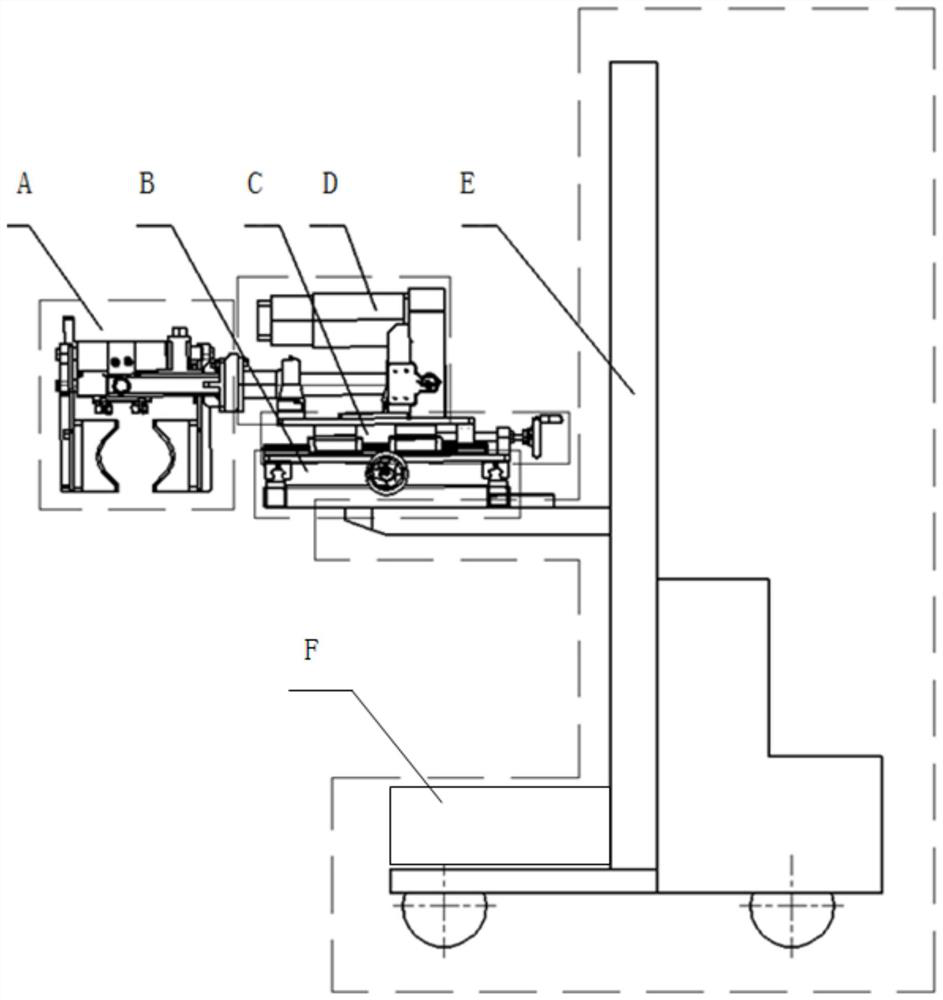
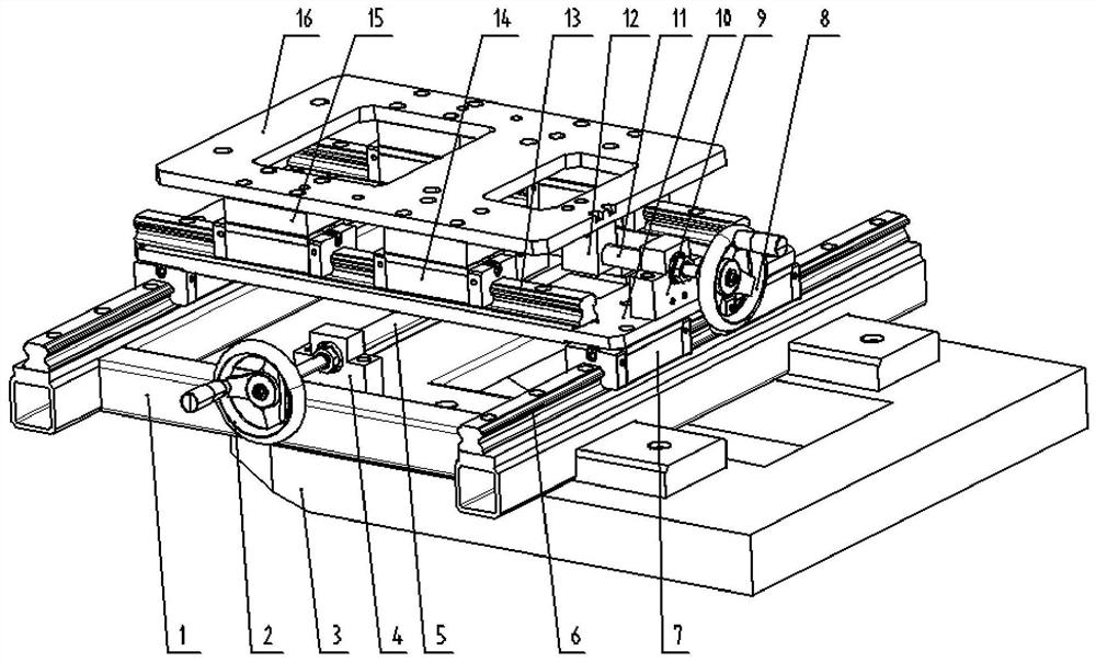
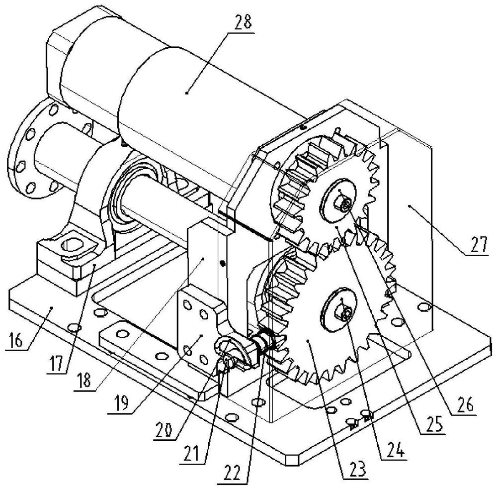
[0036] Such as Figure 1-Figure 8 As shown, the multi-degree-of-freedom grasping transmission device for special-shaped components of the aircraft landing gear includes an all-electric lifting vehicle E, a two-dimensional fine-tuning mechanism, a shaft rotation mechanism D, an attitude-adjustable clamping mechanism A, and a hydraulic system F. The two-dimensional fine-tuning mechanism is installed on the all-electric elevating vehicle E through the X-Y frame 1, the shaft rotation mechanism D is installed on the two-dimensional fine-tuning mechanism, and the attitude-adjustable clamping mechanism A is installed on the shaft rotation mechanism D At the output end, the all-electric elevati...


PUM


Abstract

The invention provides a multi-degree-of-freedom grabbing and conveying device for a special-shaped component of an aviation aircraft landing gear. The multi-degree-of-freedom grabbing and conveying device comprises a full-electric lifting walking vehicle, a two-dimensional fine adjustment mechanism, a shaft rotating mechanism, a posture-adjustable clamping mechanism and a hydraulic system, wherein the two-dimensional fine adjustment mechanism is arranged on the full-electric lifting walking vehicle through an X-Y machine base, and the shaft rotating mechanism is arranged on the two-dimensional fine adjustment mechanism; and the posture-adjustable clamping mechanism is arranged at the output end of the shaft rotating mechanism. The full-electric lifting walking vehicle drives the two-dimensional fine adjustment mechanism to walk and ascend and descend in the Z-axis direction, and the two-dimensional fine adjustment mechanism achieves X-axis and Y-axis displacement adjustment. The shaft rotating mechanism drives the posture-adjustable clamping mechanism to rotate by 360 degrees in the space, the posture-adjustable clamping mechanism horizontally grabs or vertically grabs the special-shaped component, and the hydraulic system drives the posture-adjustable clamping mechanism to act. According to the multi-degree-of-freedom grabbing and conveying device, manpower resources can be greatly saved, self-walking and multi-angle grabbing without site limitation is achieved, posture transfer is freely adjusted according to requirements, and an external power source does not need to be arranged.

Description

technical field [0001] The invention belongs to the field of aviation mechanical equipment, and in particular relates to a multi-degree-of-freedom grasping and conveying device for special-shaped components of aircraft landing gear. Background technique [0002] With the rapid development of science and technology and the continuous improvement of production levels, people have higher and higher requirements for labor intensity and working environment. Petrochemical, food, military machinery and other industries have higher and higher requirements for handling quality and efficiency. However, the inefficient manual handling has hindered the increase of the output of these industries, which can no longer meet the needs of production, thus promoting the transformation of enterprises to modernization. At present, most of the domestic automatic handling equipment are imported products, and there are relatively few domestic equipment manufacturers. The technology of handling robo...

Claims


Application Information

Patent Timeline
Patent Type & Authority Applications(China)
IPC IPC(8): B66F9/12B66F9/14B66F9/18B66F9/22B66F9/24B66F9/075
CPCB66F9/122B66F9/125B66F9/14B66F9/18B66F9/22B66F9/24B66F9/075
Inventor 刘广东阿衍学胡成昕李彦光刘心宇曹阳王松波穆祥贞吉有胜王禹刘斌暴永明高慧马忠臣屈铁军张银铃蓝乐蔡宇刘相岚
Owner 黑龙江省机械科学研究院
Why Eureka
Eureka Blog
Learn More