Arched bent suspension bridge structure

A bridge structure and bent frame technology, which is applied in bridges, suspension bridges, bridge construction, etc., can solve the problems of occupying a lot of land, and achieve the effect of beautiful structure, flexible layout and low cost

Pending Publication Date: 2021-09-24
CCCC FIRST HIGHWAY CONSULTANTS
View PDF9 Cites 2 Cited by
  • Summary
  • Abstract
  • Description
  • Claims
  • Application Information

AI Technical Summary

Problems solved by technology

[0005] The object of the present invention is to provide an arched bent suspension bridge structure, which spans the main bridge through multiple sets of transverse arch ribs, in view of the problem that a large number of piers need to be set up in the girder bridge of the prior art, and there is a problem of occupying a large amount of land. The main girder is lifted by a vertical sling, so that no pier can be set in a certain section of the main girder along the longitudinal direction of the main girder, especially suitable for roads on the ground below the main girder, pipelines under the ground, subways, etc. Situations where piers are not suitable

Method used


Image

  • Arched bent suspension bridge structure
  • Arched bent suspension bridge structure
  • Arched bent suspension bridge structure

Examples


Embodiment 1

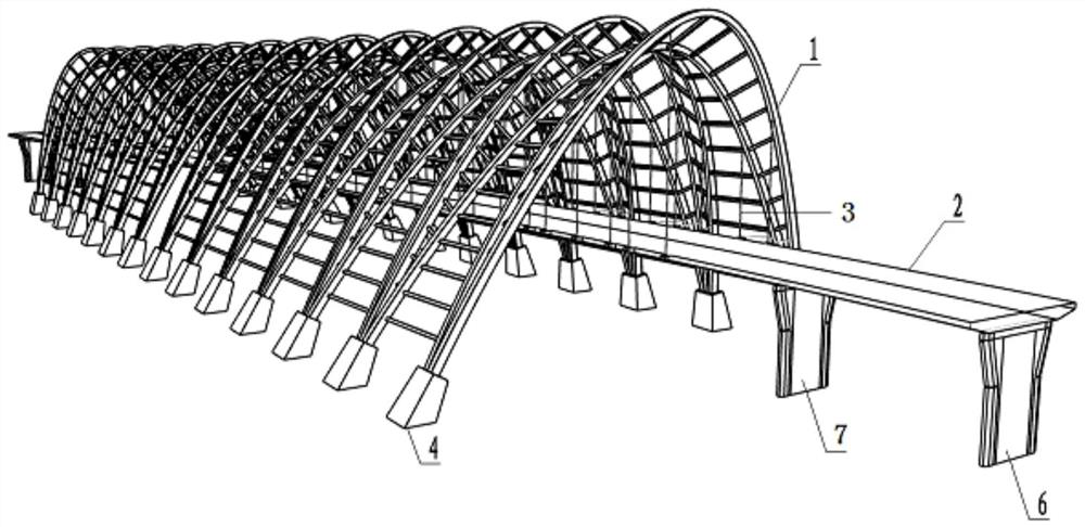
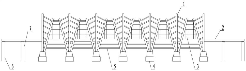
[0085] The present invention relates to an arch-bent suspension bridge structure, which comprises a longitudinal main girder 2 supported by side piers 6 below, or side piers 6 and auxiliary piers 7 . A plurality of sets of horizontal and parallel arch ribs 1 are arranged above the main beam 2 and span the main beam 2 , and vertical slings 3 are arranged between the arch ribs 1 and the main beam 2 .

[0086] The arch rib 1 includes three arc-shaped arches 11 , the middle arch 11 is vertical, the arches 11 on both sides are inclined outward, and multiple ribs 12 are arranged between adjacent arches 11 . like figure 2 Arch rib 1 located in the middle.

[0087] The arch rib 1 may also include two arc-shaped arches 11, the two arches 11 are vertical or outwardly inclined, and multiple ribs 12 are arranged between them. like Figure 4 Arch ribs in 1.

[0088] The arch rib 1 may also include two arc-shaped arch frames 11, one arch frame 11 is vertical, the other arch frame 11 is...

Embodiment 2

[0102] In this embodiment, the arch ribs 1 in Embodiment 1 are changed to two arches 11 in each group, and the two arches 11 are respectively inclined to both sides and connected by vertical braces 5 . The rest of the structure is the same as in Example 1.

Embodiment 3

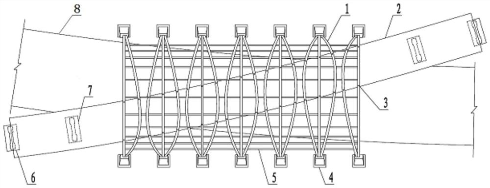
[0104] Figure 4 It is the plan view of the main structure of Example 3, and the system consists of arch ribs 1, main beams 2, slings 3, abutment foundations 4, longitudinal braces 5, and side piers 6.

[0105] The arch rib 1 adopts a circular steel pipe cross-section, and the two arch frames 11 are arranged in parallel, and are connected by a number of vertical braces 5, which adopt a circular steel pipe cross-section. The two arches 11 share a set of abutment foundations 4, the abutment foundations 4 are respectively located on both sides of the sideline of the road 8 on the ground floor, and the arch rib 1 crosses the road 8 on the ground floor horizontally. Several groups of above-mentioned arches are arranged along the route direction of the road 8 on the ground floor, some of which are arranged parallel to each other, and some of which are arranged at a certain angle with the front group of arches to adapt to the plane alignment of the main beam 2. Each group of arches ...


PUM


Abstract

The invention relates to an arched bent suspension bridge structure which comprises a longitudinal main beam, a plurality of groups of transverse arch ribs are arranged on the main beam and stretch across the main beam, and vertical slings are arranged between the arch ribs and the main beam. The arch ribs stretch across the main beam, and the two ends of the arch ribs are provided with stress points, for example, the ground serves as the stress points. Vertical slings are arranged on the arch ribs, the slings take the arch ribs as stress points and provide upward pulling force for the main beam, so that no pier is arranged in a certain section of longitudinal range of the main beam, and the structure is particularly suitable for the conditions that roads are arranged on the ground below the main beam, pipelines and subways are arranged under the ground, and piers are not suitable for being arranged.

Description

technical field [0001] The invention belongs to the technical field of bridge engineering, and in particular relates to an arch bent suspension bridge structure. Background technique [0002] With the continuous advancement of urbanization, the demand for expansion of existing roads is increasing day by day. The three-dimensional expansion and reconstruction of urban roads has become the most direct and effective way to solve road congestion in deeply urbanized areas. In the process of three-dimensional reconstruction and expansion, three-dimensional bridges often need to cross the ground layer roads repeatedly due to constraints such as terrain and features. For example, when the angle between the three-dimensional bridge and the ground road does not exceed 20°, in this case, it can reduce the land occupation, but it will increase the main force of the three-dimensional bridge crossing the ground road. Therefore, it is very difficult to set up a three-dimensional bridge on...

Claims


Application Information

Patent Timeline
Patent Type & Authority Applications(China)
IPC IPC(8): E01D11/02E01D2/00E01D19/00E01D19/02E01D19/12E01D19/16
CPCE01D11/02E01D2/00E01D19/00E01D19/02E01D19/125E01D19/16
Inventor 侯旭冯云成翟晓亮杨雨豪郭聪敏豆飞何磊齐一鸣
Owner CCCC FIRST HIGHWAY CONSULTANTS
Why Eureka
Try Eureka