Display device and power supply circuit
A technology of a display device and a power supply circuit, which is applied in the electronic field, can solve the problems of large area, large voltage stress, and high cost of the power supply circuit, and achieves the effect of reducing cost and area
- Summary
- Abstract
- Description
- Claims
- Application Information
AI Technical Summary
Problems solved by technology
Method used
Image
Examples
Embodiment 1
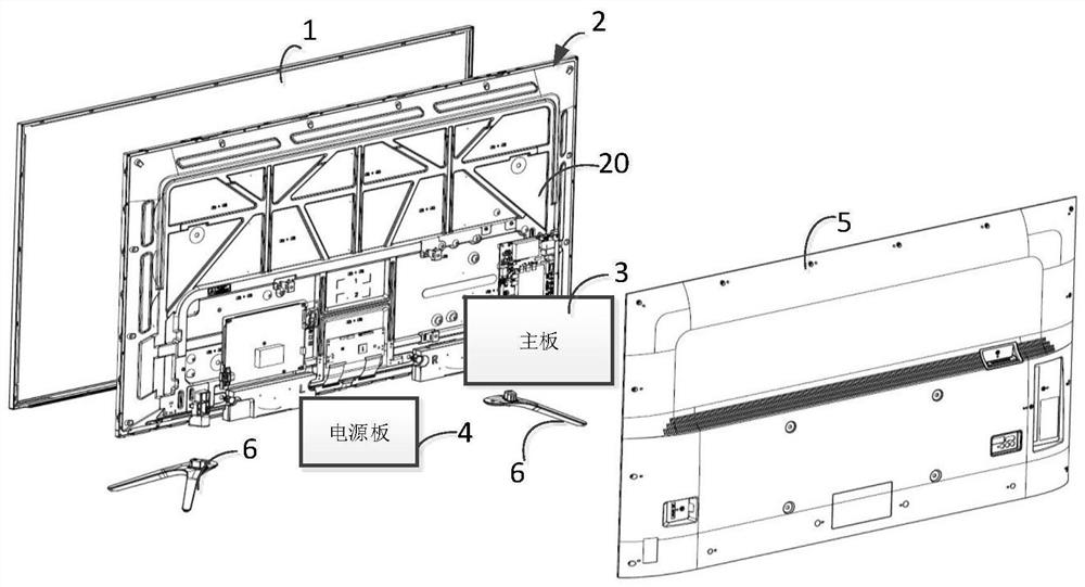
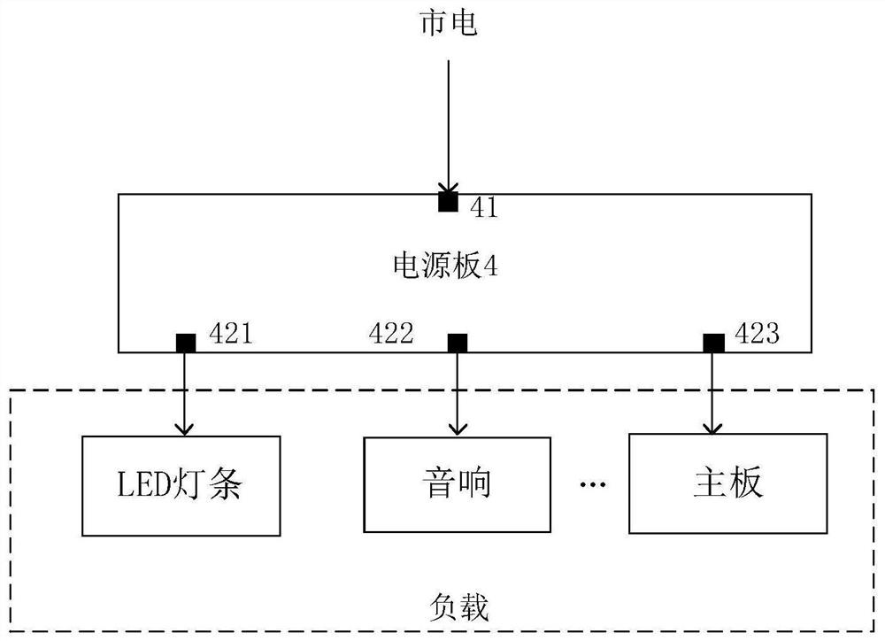
[0072] Figure 5 A schematic structural diagram of a power supply circuit of a display device provided in Embodiment 1 of the present application, wherein the power supply circuit can be applied in such as Figure 1-3 In any of the display devices, such as Figure 5 As shown, the power supply circuit provided by this embodiment includes: a power supply 11 , a filter and rectifier module 12 , a PFC module 13 , an LLC module 14 and a load. Wherein, the load includes at least the main board 18 and the multi-channel LED light bar shown in the figure.
[0073] Specifically, after the LLC module 14 of the power supply circuit provided in this embodiment receives the DC voltage sent by the PFC module 13 through the primary winding 141, different secondary windings output different voltages according to the voltage of the primary winding 141 to supply power to different loads. For example, the secondary winding 144 supplies a voltage of 12V to the motherboard 18 according to the vol...
Embodiment 2
[0083] Image 6 A schematic structural diagram of a power supply circuit of a display device provided in Embodiment 2 of the present application, wherein the power supply circuit can be applied in such as Figure 1-3 In any of the display devices, such as Image 6 The power supply circuit shown with Figure 5 The power supply circuits shown all adopt the idea of setting two different voltages output by two different secondary windings respectively, and the voltage adjustment module only needs to adjust the output voltage of the secondary winding with a smaller voltage. The only difference is that, Image 6 In the shown embodiment, the power supply circuit adopts a single flyback structure, and the first secondary winding and the second secondary winding are set to output voltage through the primary winding in the single flyback structure, while Figure 5 The first secondary winding and the second secondary winding set in the illustrated embodiment are based on the output ...
Embodiment 3
[0085] Figure 7 A schematic structural diagram of a power supply circuit of a display device provided in Embodiment 3 of the present application, wherein the power supply circuit can also be applied in such as Figure 1-3 In any one of the display devices, such as Figure 7 In the power supply circuit shown, the Figure 5 On the basis of the power supply circuit shown, connect the output terminal of the first secondary winding to the input terminal of the second secondary winding, and supply power to multiple LED strips through the output terminal of the second secondary winding. At this time, for the voltage The output voltage of the first secondary winding adjusted by the adjustment module, its input terminal is grounded instead of floating, so in Figure 7 In the illustrated embodiment, the optocoupler may not be provided to perform optocoupler isolation for the feedback signal.
[0086] Specifically, such as Figure 7 The LLC module of the power supply circuit shown i...
PUM
 Abstract
Description
Claims
Application Information
 - R&D
- Intellectual Property
- Life Sciences
- Materials
- Tech Scout
- Unparalleled Data Quality
- Higher Quality Content
- 60% Fewer Hallucinations
Browse by: Latest US Patents, China's latest patents, Technical Efficacy Thesaurus, Application Domain, Technology Topic, Popular Technical Reports.
© 2025 PatSnap. All rights reserved.Legal|Privacy policy|Modern Slavery Act Transparency Statement|Sitemap|About US| Contact US: help@patsnap.com


