Circularly polarized microstrip antenna and antenna array

A microstrip antenna, circularly polarized technology, applied to antenna arrays, individually powered antenna arrays, antennas, etc., can solve problems such as pattern shift, widen the axial ratio bandwidth, narrow the beam angle, and reduce side lobes level effect

Active Publication Date: 2021-09-24
BEIJING SUREKAM CORP
View PDF4 Cites 0 Cited by
  • Summary
  • Abstract
  • Description
  • Claims
  • Application Information

AI Technical Summary

Problems solved by technology

The series feeding structure is compact and small in size, but when the scheme has a large number of series series, the feeding network will have an impact on the antenna pattern, and as the frequency changes, the phase change of the feeding network will cause the pattern to shift

Method used


Image

  • Circularly polarized microstrip antenna and antenna array
  • Circularly polarized microstrip antenna and antenna array
  • Circularly polarized microstrip antenna and antenna array

Examples


Embodiment Construction

[0022] In order to make the object, technical solution and advantages of the present invention clearer, the present invention will be further described in detail below in conjunction with the accompanying drawings and embodiments. It should be understood that the specific embodiments described here are only used to explain the present invention, not to limit the present invention.

[0023] It can be understood that the terms "first", "second" and the like used in this application may be used to describe various elements herein, but these elements are not limited by these terms. These terms are only used to distinguish one element from another element.

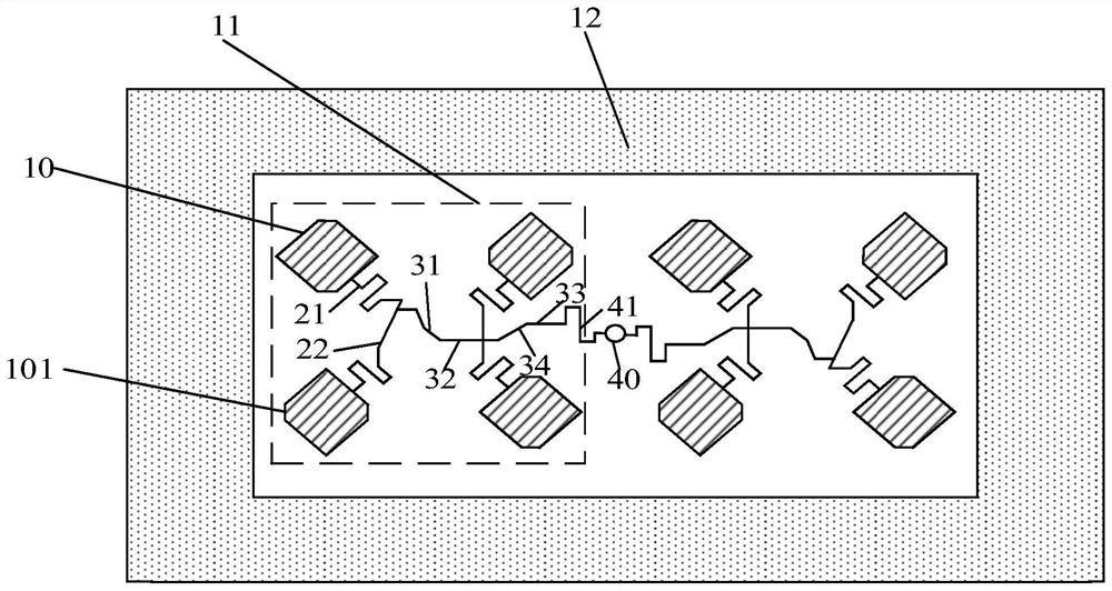
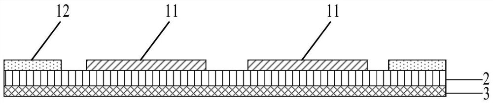
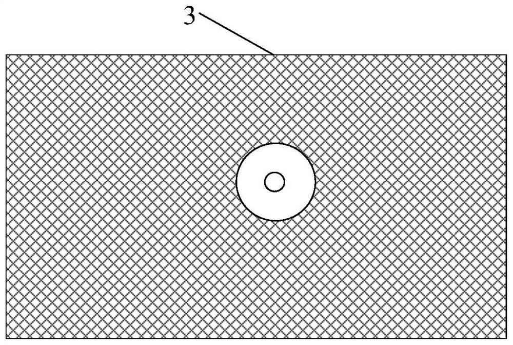
[0024] like Figures 1 to 3 As shown, in one embodiment, a circularly polarized microstrip antenna is provided, an insulating layer, a metal ground layer arranged on one side of the insulating layer, and a metal radiation element arranged on the other side of the insulating layer and used for the metal radiation element Feed ...


PUM


Abstract

The invention relates to a circularly polarized microstrip antenna which comprises an insulating layer, a metal grounding layer arranged on one side of the insulating layer, a metal radiation oscillator arranged on the other side of the insulating layer and a feed network used for feeding the metal radiation oscillator, the metal radiation oscillator comprises 4N metal patches, every four metal patches form a basic small array, the centers of the four metal patches of the basic small array are arranged on the same circumference, the feed network comprises microstrip lines in one-to-one correspondence with the metal patches, one end of each microstrip line is connected with the corresponding metal patch, the other end of each microstrip line is connected with an impedance converter, and the impedance converter is connected with an antenna array port; the phase difference generated by spatial rotation of the metal patches is compensated through microstrip line phase delay; and radio frequency signal energy is divided into different magnitudes by using the impedance transformer, and the radio frequency signal energy is sequentially transmitted to the metal patches in a clockwise or anticlockwise direction. The microstrip antenna is low in sidelobe, narrow in wave beam, high in gain, small in size and large in axial ratio bandwidth.

Description

technical field [0001] The invention relates to the field of antennas, in particular to circularly polarized microstrip antennas and antenna arrays. Background technique [0002] In the field of intelligent transportation, dedicated short-range wireless communication DSRC has high requirements on the range of signal coverage. It is hoped that a small antenna area in the RSU can be used to achieve high gain, low sidelobe, narrow beam, and circularly polarized antenna performance. The array of microstrip antennas is formed, and the pattern of the antenna array is designed comprehensively through phase and power distribution. [0003] In the feed network design of the microstrip antenna array, the commonly used feed networks include parallel feed and series feed. Parallel feed is easy to realize equal-amplitude in-phase feed and unequal-amplitude in-phase feed design, but the antenna pattern is often distorted because of the long feed network. In equal-amplitude in-phase feed,...

Claims


Application Information

Patent Timeline
Patent Type & Authority Applications(China)
IPC IPC(8): H01Q1/38H01Q1/48H01Q1/50H01Q21/00H01Q21/20H01Q21/06
CPCH01Q1/38H01Q1/48H01Q1/50H01Q21/0075H01Q21/20H01Q21/065
Inventor 井立曹坤李彦明夏曙东
Owner BEIJING SUREKAM CORP
Why Eureka
Try Eureka