Ultrasonic osteotome clamping device of spinal surgery robot

A surgical robot and clamping device technology, applied in the field of surgical robots, can solve the problems of inability to guarantee surgical accuracy and surgical stability, and achieve the effect of improving accuracy and stability and being widely used

Active Publication Date: 2021-09-28
HARBIN INST OF TECH
View PDF24 Cites 0 Cited by
  • Summary
  • Abstract
  • Description
  • Claims
  • Application Information

AI Technical Summary

Problems solved by technology

[0004] The purpose of the present invention is to solve the existing spinal surgery because the operator holds it in hand, the requirements for the operator's operating experience and operational stability are relatively high, and there are surgical Accuracy and surgical stability cannot be guaranteed

Method used


Image

  • Ultrasonic osteotome clamping device of spinal surgery robot
  • Ultrasonic osteotome clamping device of spinal surgery robot
  • Ultrasonic osteotome clamping device of spinal surgery robot

Examples


specific Embodiment approach 1

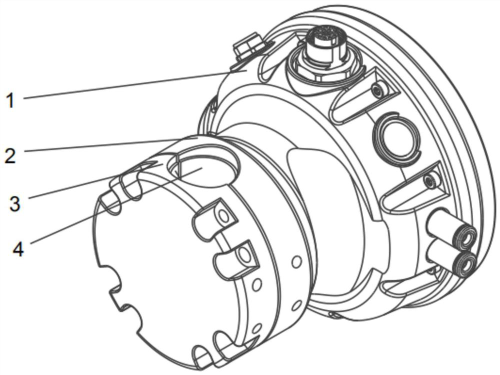
[0010] Specific implementation mode one: combine Figure 1 to Figure 11 Describe this embodiment. This embodiment includes a mechanical connection end 1, a bone knife support base 2, a locking end 3 and a clamping sleeve 4. The mechanical connection end 1 is connected to the end effector of a spinal surgery robot, and the bone knife support base 2 is installed On the mechanical connection end 1, the locking end 3 is buckled and installed on the bone knife support base 2, and the locking end 3 is buckled with the bone knife support base 2 to form a mounting hole 5, and the clamping sleeve 4 is installed in the mounting hole 5, the bone knife is embedded in the clamping sleeve 4, and the clamping sleeve 4 and the bone knife are clamped by bolts between the bone knife support seat 2 and the locking end 3.

[0011] The structure of this embodiment is simple, and it is matched with the end effector of the spinal surgery robot when it is in use. The tightening degree of bolt contro...

specific Embodiment approach 2

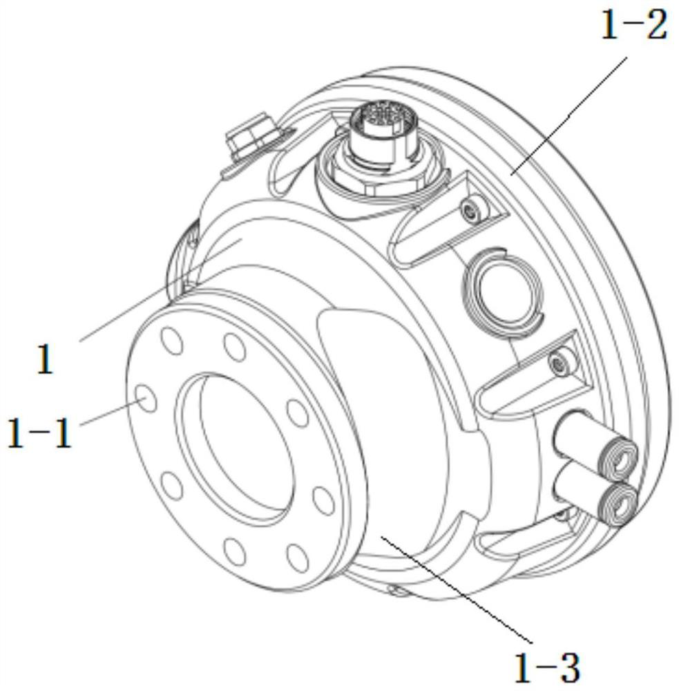
[0013] Specific implementation mode two: combination figure 2 Describe this embodiment, the mechanical connection end 1 of this embodiment includes a connecting part 1-2 and a mounting part 1-3, both of which are cylindrical, and the mounting part 1-3 is mounted on the connecting part 1-2, the connecting part 1-2 is connected to the end effector of the spinal surgery robot, and the outer diameter of the connecting part 1-2 is smaller than the outer diameter of the mounting part 1-3. Such setting facilitates the connection with the end effector of the spinal surgery robot and the bone knife support base 2 to play the role of connection and fixation. Other compositions and connections are the same as in the first embodiment.

specific Embodiment approach 3

[0014] Specific implementation mode three: combination figure 2 To describe this embodiment, a plurality of connecting threaded holes 1-1 are opened in an annular array on the side end surface of the mounting portion 1-3 in this embodiment. Set up like this for easy connection. Other compositions and connections are the same as those in Embodiment 1 or Embodiment 2.


PUM


Abstract

The invention discloses an ultrasonic osteotome clamping device of a spinal surgery robot, and relates to a positioning mechanical arm. The invention aims to solve the problems that due to the fact that an operator holds an ultrasonic osteotome with hands, the existing spinal surgery has high requirements on the operation experience and the operation stability of the operator and has the problems that operation precision and the operation stability cannot be guaranteed. A mechanical connecting end (1) of the ultrasonic osteotome clamping device is connected with an end executor of the spinal surgery robot; an osteotome supporting seat (2) is installed at the mechanical connecting end (1); a locking end (3) is installed on the osteotome supporting seat (2) in a buckled mode; an installation hole (5) is formed after the locking end (3) and the osteotome supporting seat (2) are buckled; a clamping sleeve (4) is installed in the installation hole (5); an osteotome is embedded in the clamping sleeve (4); and the clamping sleeve (4) and the osteotome are clamped between the osteotome supporting seat (2) and the locking end (3) through a bolt. The ultrasonic osteotome clamping device is used for clamping the ultrasonic osteotome.

Description

technical field [0001] The invention relates to a clamping device, in particular to a spine surgery robot ultrasonic bone knife clamping device, which belongs to the technical field of surgical robots. Background technique [0002] Clinical operation results have shown that compared with traditional spinal surgery instruments such as traditional bone knife, high-speed drill, and rongeur, ultrasonic bone knife can cut bone efficiently and accurately, and can better reduce nerves, blood vessels and other soft tissues. It reduces the risk of injury, improves the safety of the operation and the recovery speed of the patient, so it has been widely used in spinal surgery. However, the current operation method is still that the doctor holds the ultrasonic bone knife to complete the cutting process, which requires high operating experience and operational stability for the operator, and the accuracy and stability cannot be guaranteed. [0003] To sum up, the existing spinal surgery...

Claims


Application Information

Patent Timeline
IPC IPC(8): A61B34/30A61B17/32A61B90/50
CPCA61B34/30A61B17/320068A61B90/50A61B2034/305
Inventor 杨嘉辉张赫赵杰陈志刚
Owner HARBIN INST OF TECH
Why Eureka
Try Eureka