Check patentability & draft patents in minutes with Patsnap Eureka AI!

Composite leg-foot mechanism and 3-ups parallel wheel-foot composite bouncing robot

A 3-UPS, robot technology, applied in the field of robots, can solve the problems of lack of composite robots and slow development, and achieve the effect of improving flexibility and increasing bearing capacity

Active Publication Date: 2022-05-17
SHANDONG UNIV
View PDF0 Cites 0 Cited by
  • Summary
  • Abstract
  • Description
  • Claims
  • Application Information

AI Technical Summary

Problems solved by technology

[0004] However, the development of the field of compound motion robots is relatively slow at present, and there is a lack of compound robots that can operate in multiple motion modes.

Method used


Image

  • Composite leg-foot mechanism and 3-ups parallel wheel-foot composite bouncing robot
  • Composite leg-foot mechanism and 3-ups parallel wheel-foot composite bouncing robot
  • Composite leg-foot mechanism and 3-ups parallel wheel-foot composite bouncing robot

Examples


Embodiment Construction

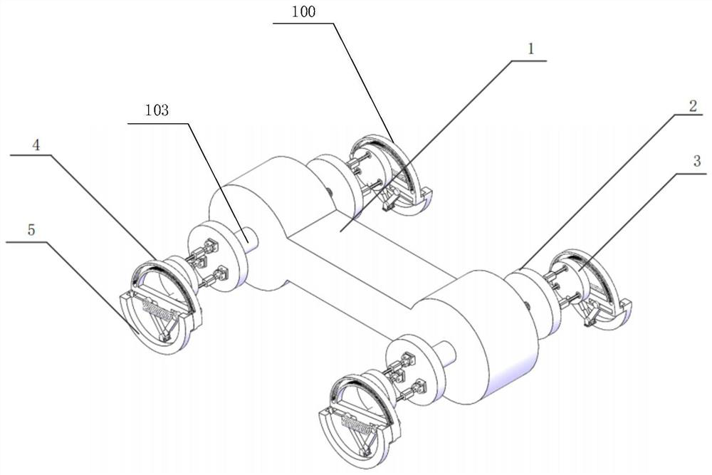
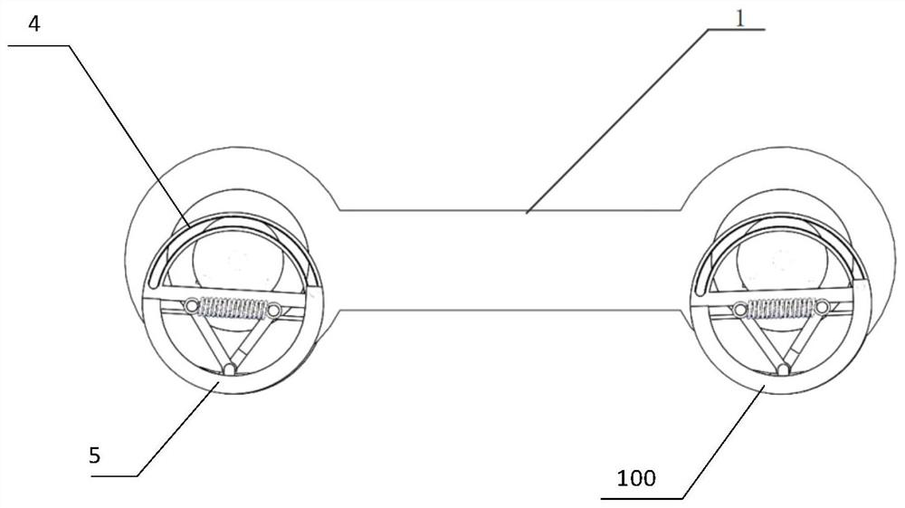
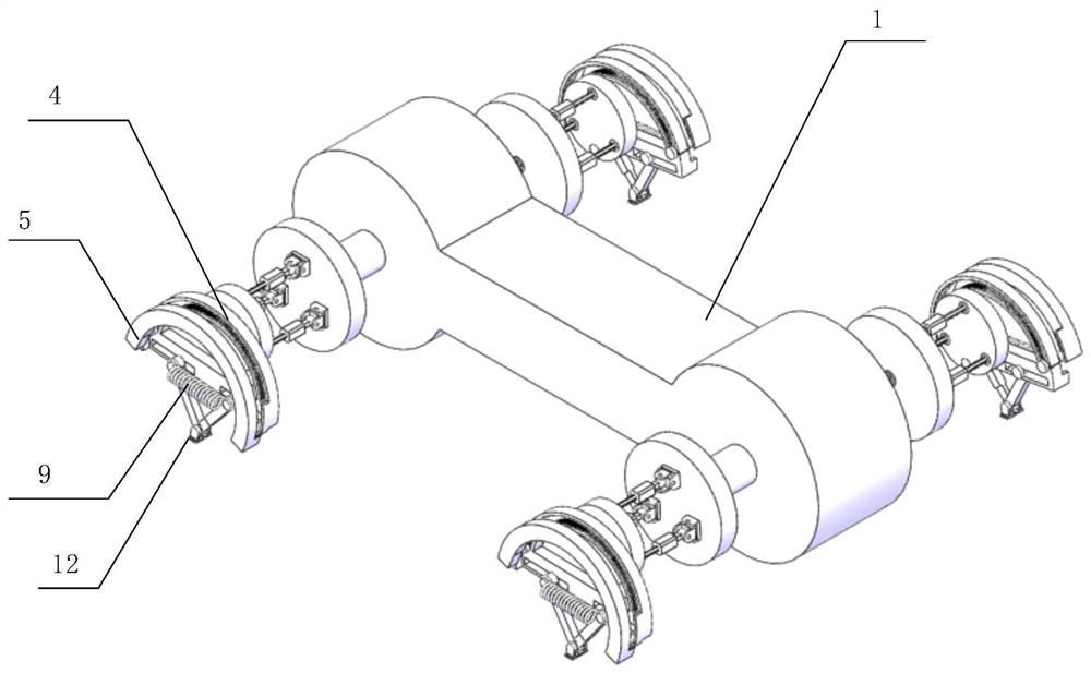
[0029] Such as Figure 1 to Figure 9 Shown:

[0030] The 3-UPS parallel wheel-foot composite bouncing robot of the present invention includes a fuselage 1 and composite leg-foot mechanisms arranged symmetrically on both sides of the fuselage 1 . In this embodiment, the fuselage 1 is in the shape of a dumbbell, and there are 4 sets of composite leg-foot mechanisms, which are placed on both sides of the fuselage 1 in pairs. The structure of one group of compound leg-foot mechanisms is taken as an example below, and the other three groups are the same, and will not be described in detail.

[0031] The composite leg-foot mechanism includes an upper semi-circular ring 4, a lower semi-circular ring 5, a static platform 2, a parallel swing mechanism, and a dynamic platform 3. A threaded rod 103 is fixedly threaded at both ends of the long axis of the fuselage 1, and the two ends of the threaded rod 103 protrude from the fuselage 1 and are fixedly connected to a static platform 2, s...


PUM


Abstract

The compound leg-foot mechanism and 3-UPS parallel wheel-foot composite bouncing robot of the present invention, wherein, the compound leg-foot mechanism includes an upper half ring, a lower half ring, and a parallel swing mechanism, the upper half ring, the lower half When the rings are spliced ​​into rings, wheels are formed, which not only realizes wheel-type movement but also realizes foot-type walking under the control of the parallel swing mechanism; when the upper half ring and the lower half ring overlap, bouncing movement is realized. Its purpose is to provide a compound leg-foot mechanism and a 3-UPS parallel wheel-foot compound bouncing robot with high flexibility and strong bearing capacity suitable for lunar rugged ground exploration.

Description

technical field [0001] The invention relates to a robot with a driving and walking propulsion device, in particular to a composite leg-foot mechanism and a 3-UPS parallel wheel-foot composite bouncing robot. Background technique [0002] Quadruped walking robots can be divided into series, parallel and hybrid robots according to the different leg structures. Most of the existing wheel-foot composite robots or bouncing robots use joint connection in series, which results in defects in the load capacity and dynamic characteristics of the foot end of the single leg. A mobile robot based on a series structure has a small leg stiffness and cannot undertake tasks with high load-bearing requirements; the cumulative error of the series joints affects the motion accuracy of the foot of the robot's single leg; if a high-load hydraulic structure is used, hydraulically driven noise will be generated problems as well as reduced mobility on one leg. [0003] Mobile robots are divided in...

Claims


Application Information

Patent Timeline
IPC IPC(8): B62D57/028
CPCB62D57/028
Inventor 姚云龙刘思民马广英李鸿博张玉妍
Owner SHANDONG UNIV
Features
  • R&D
  • Intellectual Property
  • Life Sciences
  • Materials
  • Tech Scout
  • Unparalleled Data Quality
  • Higher Quality Content
  • 60% Fewer Hallucinations
Learn More