Independent temperature and humidity control system for plant cabin in severe cold area

An independent control, temperature and humidity technology, applied in the direction of botanical equipment and methods, applications, refrigerators, etc., to achieve the effect of improving evaporation heat transfer efficiency, reducing floor space and installation space, and large heat exchange area

Pending Publication Date: 2021-09-28
TONGJI UNIV
View PDF9 Cites 1 Cited by
  • Summary
  • Abstract
  • Description
  • Claims
  • Application Information

AI Technical Summary

Problems solved by technology

[0006] The purpose of the present invention is to provide an independent temperature and humidity control system for plant cabins in severe cold regions in order to overcome the defects of the above-mentioned prior art, which solves the problem of independent and efficient control of indoor temperature and humidity

Method used


Image

  • Independent temperature and humidity control system for plant cabin in severe cold area
  • Independent temperature and humidity control system for plant cabin in severe cold area

Examples


Embodiment 1

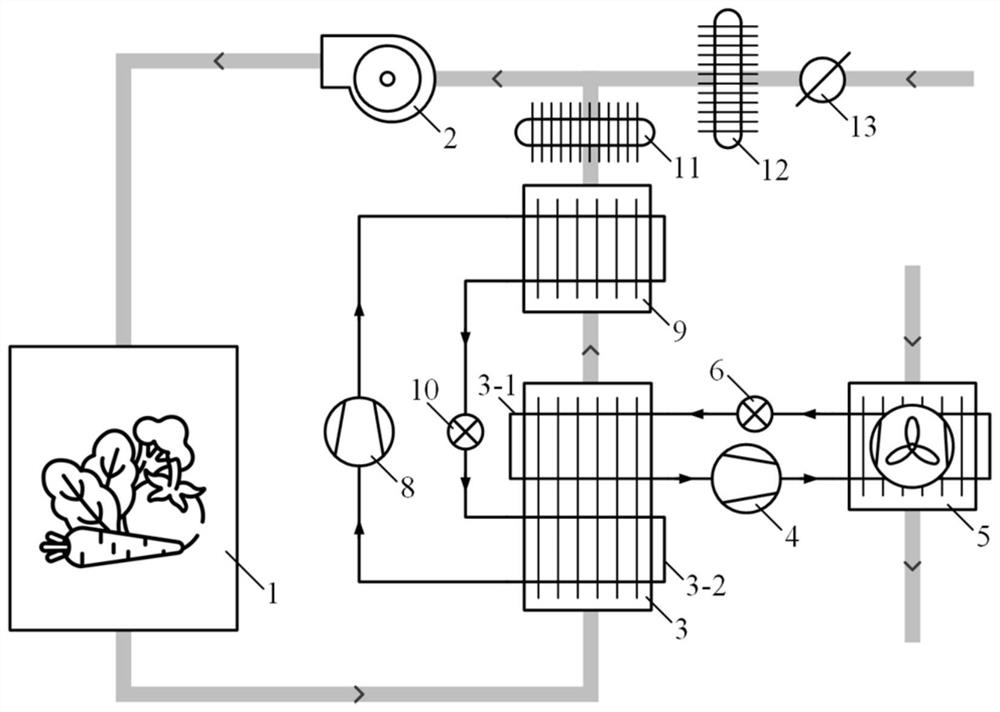
[0045] The present invention is used for the temperature and humidity independent control system of the plant cabin in severe cold area (referring to figure 1 ), including the first refrigerant circulation flow path (refrigeration system) for temperature regulation, the second refrigerant circulation flow path (dehumidification system) for humidity regulation, the air circulation flow path in the plant cabin, the outdoor fresh air flow path, and the outdoor air cooling flow road.

[0046] The first refrigerant circulation flow path for temperature regulation, including the refrigeration system refrigerant evaporation heat exchange pipeline 3-1 of the joint evaporator 3, the refrigeration system compressor 4, the refrigerant channel of the refrigeration system condenser 5 and the refrigeration system connected in sequence The system throttling element 6, the refrigeration system throttling element 6 is connected with the refrigeration system refrigerant evaporation heat exchang...

Embodiment 2

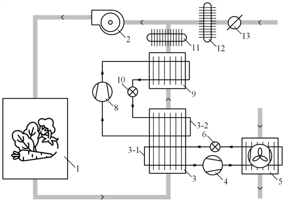
[0065] The basic principle of this embodiment is similar to Embodiment 1 (see figure 2 ), are also provided with the first refrigerant circulation flow path (refrigeration system) for temperature regulation, the second refrigerant circulation flow path (dehumidification system) for humidity regulation, air supply electric heater 11, fresh wind electric heater 12, etc.

[0066] The difference is that in the combined evaporator 3 shared by the fins, the refrigerant heat exchange pipe 3-1 of the first refrigerant circulation flow path (refrigeration system) is placed in the refrigeration of the second refrigerant circulation flow path (dehumidification system). Before the refrigerant heat exchange pipeline 3-2, that is, the return air of the plant cabin first flows through the refrigerant evaporation heat exchange pipeline 3-1 of the refrigeration system. In this embodiment, both the refrigeration system compressor 4 of the refrigeration system and the dehumidification system comp...


PUM


Abstract

The invention relates to an independent temperature and humidity control system for a plant cabin in a severe cold area. The independent temperature and humidity control system comprises a first refrigerant circulation flow path, a second refrigerant circulation flow path, an air circulation flow path in the plant cabin, an outdoor fresh air flow path and an outdoor air heat dissipation flow path, wherein an evaporator end of the first refrigerant circulating flow path is connected with the air circulating flow path in the plant cabin in a heat exchange manner to realize temperature regulation and control; an evaporator end and a condenser end of the second refrigerant circulating flow path are sequentially connected with the air circulating flow path in the plant cabin in a heat exchange manner to realize humidity regulation and control; the outdoor fresh air flow path is communicated with the air circulation flow path in the plant cabin, so that the fresh air input process is regulated and controlled; the outdoor air heat dissipation flow path is arranged at the condenser end of the first refrigerant circulation flow path. Compared with the prior art, a set of steam compression type dehumidification system is integrated, independent and accurate control over humidity can be achieved, and the dehumidification system is independent of the external environment.

Description

technical field [0001] The invention relates to an environment control system, in particular to an independent temperature and humidity control system for plant cabins in severe cold regions. Background technique [0002] Plant growth in the severe cold area of ​​northern my country is a big problem. In order to meet the demand for local vegetable supply and alleviate the difficulties of long-distance logistics and transportation, the use of container-type plant cabins and supporting temperature control systems has become a hot spot in recent years. [0003] Different from mild climate areas, the environmental control inside the plant cabin in severe cold areas faces greater difficulties: ①The temperature difference between day and night and season is large. In winter, the outdoor temperature can be as low as minus 30°C and requires heating, while in summer, the highest temperature can be reached outdoors at noon. 35°C requires refrigeration. ②Due to plant transpiration, t...

Claims


Application Information

Patent Timeline
Patent Type & Authority Applications(China)
IPC IPC(8): F25B41/40F25B49/02A01G9/24
CPCF25B41/40F25B49/02A01G9/246Y02A40/25
Inventor 成家豪曹祥张春路
Owner TONGJI UNIV
Why Eureka
Try Eureka