
Lamination device for stator iron core of electric motor

A technology of iron core laminations and motor stators, which is applied in the manufacture of stator/rotor bodies, etc., can solve the problems of increasing eddy current path resistance, silicon steel sheet offset, and long time, so as to reduce motion resistance, improve efficiency, and reduce wear degree of effect

Active Publication Date: 2021-11-09
江苏苏爱尔电力设备有限公司
View PDF0 Cites 1 Cited by
  • Summary
  • Abstract
  • Description
  • Claims
  • Application Information

AI Technical Summary

Problems solved by technology

[0003] During the operation of the motor, the stator core will produce a certain eddy current loss, and in order to reduce the eddy current loss of the stator core, the stator core is usually made of silicon steel sheets that are insulated from each other, because the silicon steel sheets can make the eddy current pass through the narrow and long loop. The cross-section increases the resistance on the eddy current path, thereby reducing the eddy current loss; at present, silicon steel sheets are often superimposed into a "day" or "mouth" shape, but the following problems will occur during the forming process of the stator core laminations: common use artificial The layer-by-layer stacking of silicon steel sheets is realized by stacking one by one. This method takes a long time, and it is easier to reduce the overall forming efficiency of the stator core. When fixed, the silicon steel sheet is more likely to be offset, so that it is more likely to affect the use effect of the formed stator core

Method used


Image

  • Lamination device for stator iron core of electric motor
  • Lamination device for stator iron core of electric motor
  • Lamination device for stator iron core of electric motor

Examples


Embodiment Construction

[0030] The following will clearly and completely describe the technical solutions in the embodiments of the present invention with reference to the accompanying drawings in the embodiments of the present invention. Obviously, the described embodiments are only some, not all, embodiments of the present invention. Based on the embodiments of the present invention, all other embodiments obtained by persons of ordinary skill in the art without making creative efforts belong to the protection scope of the present invention.

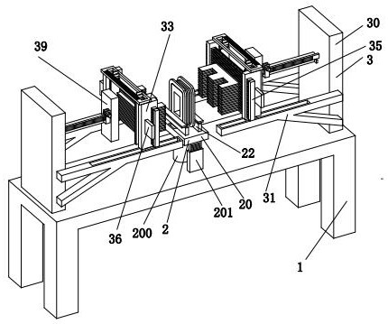
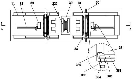
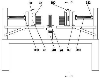
[0031] refer to figure 1 and figure 2 , a motor stator core lamination device, including a workbench 1, a fixing mechanism 2 and a lamination mechanism 3, the workbench 1 is placed on the ground, a fixing mechanism 2 is arranged in the middle of the upper end surface of the workbench 1, and the fixing mechanism Lamination mechanism 3 is arranged symmetrically on the left and right sides of 2, and lamination mechanism 3 is installed on the upper end surface o...


PUM


Abstract

The invention relates to the field of stator core processing, in particular to a motor stator core lamination device, comprising a workbench, a fixing mechanism and a lamination mechanism. The workbench is placed on the ground, and a fixing mechanism is arranged in the middle of the upper end surface of the workbench , the left and right sides of the fixing mechanism are symmetrically arranged with a lamination mechanism, which is installed on the upper end surface of the workbench. The present invention adopts the design concept of multiple pressure regulation. Layer superimposition processing, without manually stacking silicon steel sheets one by one, thereby improving the efficiency of stator core forming, and at the same time, the pressure plate set in the lamination mechanism can retain the stacked silicon steel sheets to avoid silicon steel sheets. The deflection of the sheet during the installation of the fastener affects the use effect of the subsequent stator core.

Description

technical field [0001] The invention relates to the field of stator core processing, in particular to a motor stator core lamination device. Background technique [0002] The stator is the static part of the motor. The stator is composed of three parts: the stator core, the stator winding and the machine base. The stator core is an important part that constitutes the motor magnetic flux circuit and fixes the stator coil. The fasteners are compressed to form a whole, and the stator core and rotor core, the air gap between the stator and the rotor together form a complete magnetic circuit of the motor. [0003] During the operation of the motor, the stator core will produce a certain eddy current loss, and in order to reduce the eddy current loss of the stator core, the stator core is usually made of silicon steel sheets that are insulated from each other, because the silicon steel sheets can make the eddy current pass through the narrow and long loop. The cross-section incre...

Claims


Application Information

Patent Timeline
Patent Type & Authority Patents(China)
IPC IPC(8): H02K15/02
CPCH02K15/02
Inventor 刘自国
Owner 江苏苏爱尔电力设备有限公司
Learn More