A horizontal intake and exhaust gas distribution device

A technology of intake and exhaust, horizontal placement, applied in valve devices, machines/engines, mechanical equipment, etc., can solve the problem that the arrangement of intake and exhaust valves is difficult to meet the experimental requirements, and achieve the effect of improving intake efficiency

Active Publication Date: 2022-03-11
HARBIN ENG UNIV
View PDF0 Cites 0 Cited by
  • Summary
  • Abstract
  • Description
  • Claims
  • Application Information

AI Technical Summary

Problems solved by technology

[0004] In summary, for the experimental device with multiple injectors, the existing arrangement of intake and exhaust valves is difficult to meet the experimental requirements

Method used


Image

  • A horizontal intake and exhaust gas distribution device
  • A horizontal intake and exhaust gas distribution device
  • A horizontal intake and exhaust gas distribution device

Examples


Embodiment Construction

[0018] The technical solutions in the embodiments of the present invention will be clearly and completely described below in conjunction with the drawings in the embodiments of the present invention.

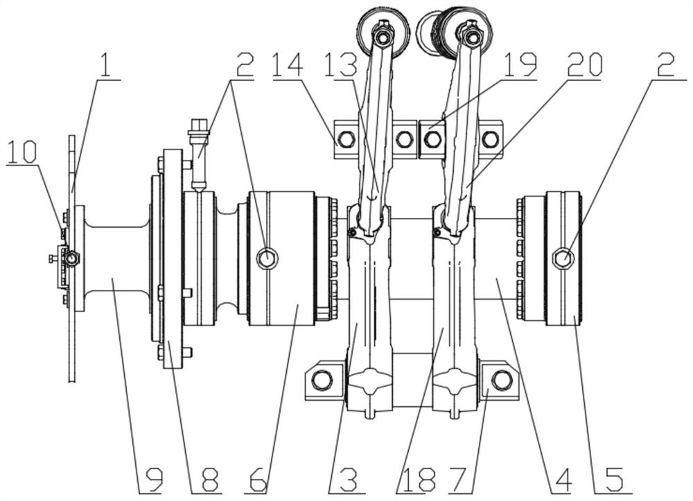
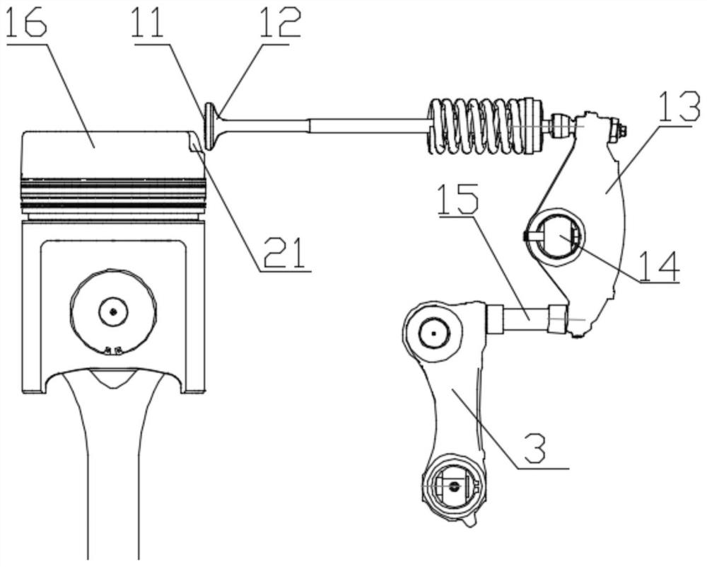
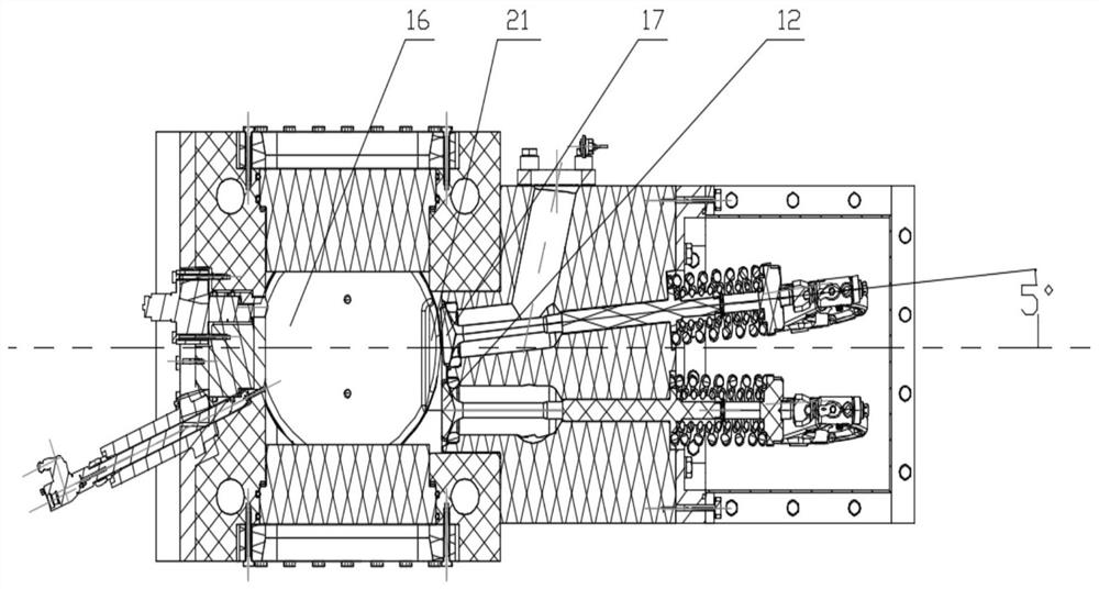
[0019] see Figure 1-3 Describe this embodiment, a horizontal intake and exhaust gas distribution device, which includes a camshaft 4, a driven shaft 7, an intake valve 17, an exhaust valve 12, an intake cam follower 18, an exhaust cam follower Part 3, intake rocker arm 20, exhaust rocker arm 13, intake push rod and exhaust push rod 15, intake cam and exhaust cam are installed on the camshaft 4, and the intake cam and exhaust The cams are in contact with the intake cam follower 18 and the exhaust cam follower 3 respectively, and the bottom ends of the intake cam follower 18 and the exhaust cam follower 3 are connected to the driven shaft 7 in rotation, The upper part of the intake cam follower 18 is connected to the bottom of the intake rocker arm 20 through the intake push rod...


PUM


Abstract

The invention provides a horizontal intake and exhaust gas distribution device, which belongs to the field of engine gas distribution mechanisms. It solves the problem that the existing arrangement of intake and exhaust valves is difficult to meet the combustion experiment. It consists of intake cams and exhaust cams mounted on the camshaft, the intake cams and exhaust cams are in contact with the intake cam follower and exhaust cam follower respectively, the intake cam follower and the exhaust cam The bottom of the follower is connected to the driven shaft in rotation, the upper part of the intake cam follower is connected to the bottom of the intake rocker arm through the intake push rod, and the middle part of the intake rocker arm is connected to the intake rocker shaft. The upper part of the rocker arm is connected with the intake valve, and the upper part of the exhaust cam follower is connected with the bottom of the exhaust rocker arm through the exhaust push rod. The intake valve and the exhaust valve are horizontally arranged perpendicular to the piston running direction. The arrangement is located below the cylinder head and above the top dead center of the piston. It is mainly used for gas distribution of the engine.

Description

technical field [0001] The invention belongs to the field of engine gas distribution mechanisms, in particular to a horizontal intake and exhaust gas distribution device. Background technique [0002] In the prior art, the engine crankshaft and the camshaft are connected by timing gears, so that the rotation of the crankshaft is synchronized with the camshaft, and the camshaft controls the opening or closing of the intake and exhaust valves by controlling mechanisms such as push rods and rocker arms. The existing valve train basically adopts overhead valve train. When the test needs to install multiple fuel injectors or glass windows on the top of the cylinder head, if the overhead valve train is used, it is not enough to arrange enough fuel injectors to simulate the combustion process of the required test, and it is not enough to arrange a large enough fuel injector. The top visualization window is used to observe the combustion process in the combustion chamber, which doe...

Claims


Application Information

Patent Timeline
Patent Type & Authority Patents(China)
IPC IPC(8): F01L1/047F02F1/22F01L3/00F02F3/28
CPCF01L1/047F02F1/22F01L3/00F02F3/28F01L2001/054F01L2003/255F01L2003/256
Inventor 刘岱周慧东熊仟刘龙张天程威嘉张琦
Owner HARBIN ENG UNIV
Why Eureka
Try Eureka