Air compression device
A technology of a compressor and an air inlet, applied in the field of compressors, can solve the problems of low pumping efficiency and low compression ratio, and achieve the effects of improving the compression ratio, improving the pumping efficiency, and improving the practical value.
- Summary
- Abstract
- Description
- Claims
- Application Information
AI Technical Summary
Problems solved by technology
Method used
Image

Examples
Embodiment Construction
[0045] In order to enable those skilled in the technical field to which the application belongs to understand the application more clearly, the technical solutions of the application will be described in detail below through specific embodiments in conjunction with the accompanying drawings.
[0046] This embodiment provides a circumferential turbine to improve the technical problems of wasting heat energy and low heat conversion efficiency in the existing internal combustion engine.
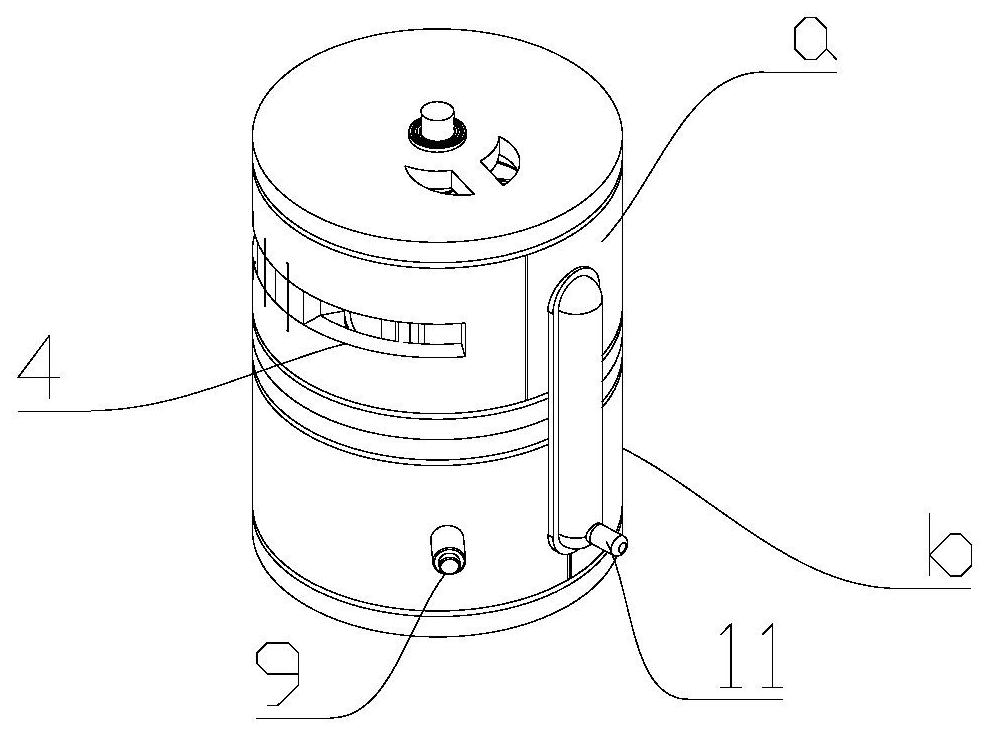
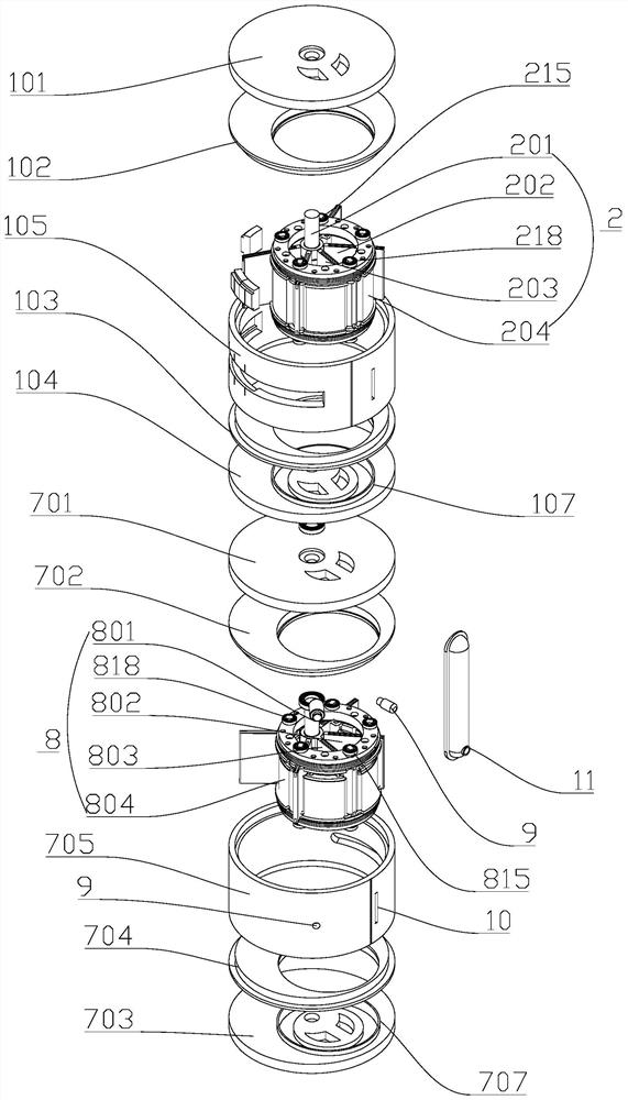
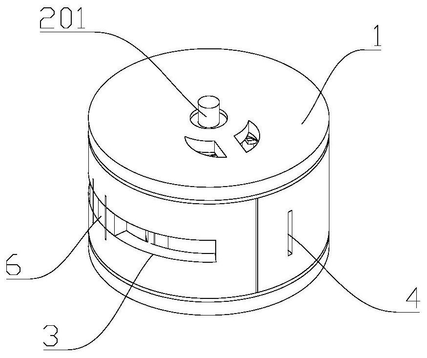
[0047] figure 1 It is a structural schematic diagram of a peripheral flow turbine of the present embodiment, figure 2 for figure 1 Explosion diagram. combine figure 1 as well as figure 2 , the peripheral flow turbine provided in this embodiment mainly includes a compressor a and a work device b, the compressor a is used to provide the high-pressure gas required for combustion to the work device b, and the work device b will deliver the high-pressure gas in the work device b The gas and co...
PUM
 Abstract
Description
Claims
Application Information