Novel airtight cabin-penetrating optical fiber connector

An optical fiber connector and airtight technology, which is applied in the field of new airtight through-chamber optical fiber connectors, can solve the problems of poor environmental resistance, easy air leakage, long connector length, etc., achieve good optical effects and ensure airtightness Effect

Pending Publication Date: 2021-10-01
SHANGHAI AEROSPACE SCI & IND ELECTRIC APPLIANCE RES INST
View PDF0 Cites 0 Cited by
  • Summary
  • Abstract
  • Description
  • Claims
  • Application Information

AI Technical Summary

Problems solved by technology

Traditional hermetic electrical connectors generally use glass sintering, but glass sintering has technical difficulties in the realization of optical fiber connectors. First of all, the glue for bonding optical fibers inside traditional optical fiber connectors cannot withstand the sintering temperature, and it is difficult to treat the end face after sintering. Guarantee, and the optical fiber contacts after glass sintering lose their floatability, which is contrary to the design principles of optical fiber connectors
[0003] Commonly used optical fiber connector glue sealing schemes have poor environmental resistance, and are prone to air leakage after experiencing high and low temperatures
Another common solution is to weld the metallized optical fiber and the sealed adapter plate, and then connect the optical fiber connector at both ends. The length of the connector is very long, the resistance to the mechanical environment is poor, and the risk of fiber breakage during the process operation is high. Low pass rate

Method used


Image

  • Novel airtight cabin-penetrating optical fiber connector
  • Novel airtight cabin-penetrating optical fiber connector
  • Novel airtight cabin-penetrating optical fiber connector

Examples


Embodiment Construction

[0029] The present invention will be further explained below in conjunction with specific embodiments.

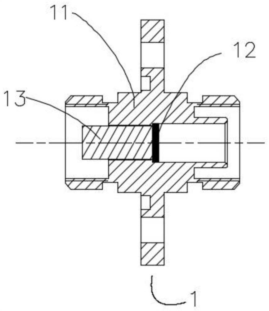
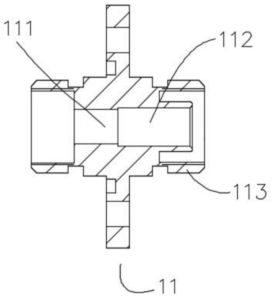
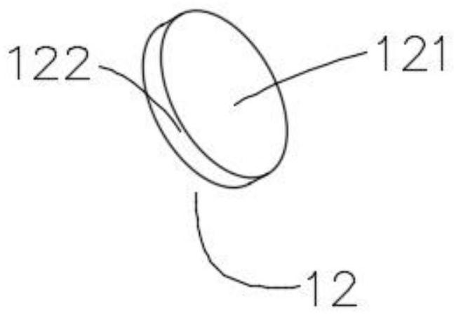
[0030] refer to Figure 1-7 , a new airtight cabin-penetrating optical fiber connector, including a socket 1 and a plug 2. The socket 1 includes a socket housing 11, one end of the socket housing 11 is provided with a collimator mounting hole 111, and the other end is provided with a front-end docking hole 112, The collimator mounting hole 111 and the front-end docking hole 112 are connected and the central axes coincide. The end of the front-end docking hole 112 close to the collimator mounting hole 111 is provided with an optical window 12, and the inner wall of the front-end docking hole 112 is provided with a gold-plated layer. The circumferential surface 122 of the window 12 is provided with a gold-plated layer, which is more conducive to welding, and the front-end butt joint hole 112 and the optical window 12 are fixedly connected by welding to meet the airtightness r...


PUM


Abstract

The invention discloses a novel airtight cabin-penetrating optical fiber connector which comprises a socket and a plug, wherein the socket comprises a socket shell, one end of the socket shell is provided with a collimator mounting hole, the other end of the socket shell is provided with a front-end butt joint hole, the collimator mounting hole and the front-end butt joint hole are communicated, the central axes of the collimator mounting hole and the front-end butt joint hole coincide, an optical window sheet is arranged at the end, which is close to the collimator mounting hole, in the front-end butt joint hole, and a socket collimator is arranged in the collimator mounting hole; and the plug comprises a plug main sleeve, one end of the plug main sleeve is provided with a front end hole, and a plug collimator is axially and movably connected in the front end hole. According to the novel airtight cabin-penetrating optical fiber connector provided by the invention, the optical window sheet is arranged on the socket, and the optical window sheet is fixed in a welding manner, so that the airtightness of the socket is ensured; and collimators are arranged on the plug and the socket, so that the transmission effect of the optical fiber is ensured.

Description

technical field [0001] The invention relates to the technical field of connectors, in particular to a novel airtight cabin-piercing optical fiber connector. Background technique [0002] With the application of optical transmission in special fields such as aerospace and precision instruments and equipment, it is urgent to solve the problem of optical signal transmission inside and outside the chamber in high vacuum or special atmosphere environment. Traditional hermetic electrical connectors generally adopt the method of glass sintering, but the glass sintering method has technical difficulties in the realization of optical fiber connectors. First, the glue for bonding the optical fibers inside the traditional optical fiber connector cannot withstand the sintering temperature, and the end surface treatment after sintering is difficult. Guaranteed, and the optical fiber contacts after glass sintering lose their floatability, which is contrary to the design principles of opti...

Claims


Application Information

Patent Timeline
Patent Type & Authority Applications(China)
IPC IPC(8): G02B6/38
CPCG02B6/3821G02B6/3849G02B6/385G02B6/3843G02B6/3873G02B6/3825G02B6/387
Inventor 陈惠钦李虎赵苏琨马永会王旭
Owner SHANGHAI AEROSPACE SCI & IND ELECTRIC APPLIANCE RES INST
Why Eureka
Try Eureka