a riveting machine

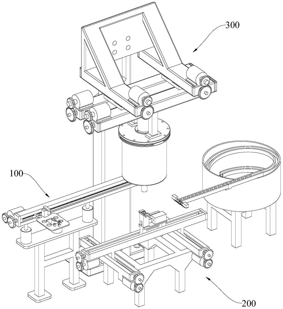
A spin riveting machine and screw technology, which is applied in the field of gearbox suspension assembly production line, can solve problems such as large assembly errors, safety accidents, and potential safety hazards, so as to improve the rotation angle and speed, reduce the difficulty of control, and improve the speed of spin riveting. effect of effect

Active Publication Date: 2022-07-08
NINGBO JIEBAO GROUP CO LTD
View PDF10 Cites 0 Cited by
  • Summary
  • Abstract
  • Description
  • Claims
  • Application Information

AI Technical Summary

Problems solved by technology

[0003] However, the existing assembly of gearbox mounts mainly has the following defects: 1. Low degree of automation, large demand for labor force, and low efficiency of manual operation; 2. Large assembly errors and high scrap rate are prone to occur during manual assembly; 3. 1. Improper manual operation or equipment failure will easily lead to safety accidents and there are potential safety hazards; 4. During the spin riveting operation, since the spinning head must realize both the pressing process and the rotating process, the existing spin riveting The riveting machine needs to be equipped with two sets of power systems in order to realize the pressing and rotating of the spinning rod at the same time, resulting in the structure of the spinning riveting machine not being compact enough, the control is difficult, and the operation is extremely inconvenient

Method used


Image

  • a riveting machine
  • a riveting machine
  • a riveting machine

Examples


Embodiment Construction

[0037] The present application will be further described below with reference to the specific embodiments. It should be noted that, under the premise of no conflict, the embodiments or technical features described below can be arbitrarily combined to form new embodiments.

[0038] In the description of this application, it should be noted that, for orientation words, such as the terms "center", "horizontal", "longitudinal", "length", "width", "thickness", "upper", "lower" , "Front", "Back", "Left", "Right", "Vertical", "Horizontal", "Top", "Bottom", "Inside", "Outside", "Clockwise", "Counterclockwise" ” etc. indicating the orientation and positional relationship are based on the orientation or positional relationship shown in the accompanying drawings, which are only for the convenience of describing the present application and simplifying the description, rather than indicating or implying that the device or element referred to must have a specific orientation or a specific or...


PUM


Abstract

The application discloses a riveting machine, comprising a second mounting frame and a riveting machine body; the riveting machine body includes a sleeve, a top cover, a spinning rod, a limit sliding rod and a drive assembly; the sleeve is the upper and lower ends Open cylindrical structure, the inner ring surface of the casing is provided with a positioning chute and a spiral chute; the spinning rod is coaxially arranged inside the casing, and the lower end of the spinning rod extends to the bottom of the casing; the limit sliding rod It is arranged along the radial direction of the sleeve, and one end of the limit sliding rod is arranged on the spinning rod and the other end is slidably connected to the positioning chute and the spiral chute; the top cover is arranged on the upper end of the sleeve and is arranged on the second mounting frame; The driving component is arranged on the top cover and is used to drive the spinning rod to move up and down; when the limit sliding rod slides in the spiral chute, the spinning rod can be forced to rotate. Only one driving component is needed to realize the pressing and rotation of the spinning rod at the same time, which is beneficial to make the structure and layout of the riveting machine more compact and ingenious, and is beneficial to reduce the difficulty of control.

Description

technical field [0001] The present application relates to the technical field of production lines, in particular to a gearbox suspension assembly production line. Background technique [0002] The existing gearbox suspension generally includes a base, a main spring, a cantilever and a bow, wherein the main spring and the cantilever are arranged between the bows. During the assembly process, it is necessary to manually assemble the rivets into the corresponding holes on the fixture, and place the base, spring, cantilever and bow on the fixture, and then transport the fixture to the riveting station to pass The riveting machine performs the riveting operation to realize the riveting between the bow and the base. [0003] However, the assembly of the existing gearbox suspension mainly has the following defects: 1. The degree of automation is low, the labor demand is large, and the efficiency of manual operation is low; 2. The manual assembly is prone to large assembly errors a...

Claims


Application Information

Patent Timeline
Patent Type & Authority Patents(China)
IPC IPC(8): B21J15/12B21J15/16B21J15/14
CPCB21J15/12B21J15/16B21J15/14
Inventor 陆兆明
Owner NINGBO JIEBAO GROUP CO LTD
Why Eureka
Try Eureka