Turbine blade sealing tooth machining clamp and clamping method thereof

A technology for turbine blades and sealing teeth, applied in the field of turbine blade sealing teeth processing fixtures and their clamping, can solve problems such as deformation and easy generation of chatter, increase system stiffness, solve high defect rate, avoid chatter and other problems. deformation effect

Inactive Publication Date: 2021-10-08
AECC AERO SCI & TECH CO LTD
View PDF10 Cites 3 Cited by
  • Summary
  • Abstract
  • Description
  • Claims
  • Application Information

AI Technical Summary

Problems solved by technology

[0003] The purpose of the present invention is to provide a fixture for machining turbine blade sealing teeth and its clamping method, so as to solve the problem that the existing turbine blade sealing teeth are prone to vibration and deformation

Method used


Image

  • Turbine blade sealing tooth machining clamp and clamping method thereof
  • Turbine blade sealing tooth machining clamp and clamping method thereof
  • Turbine blade sealing tooth machining clamp and clamping method thereof

Examples


Embodiment

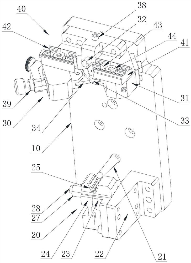
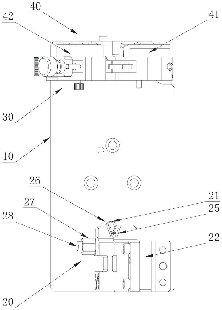
[0048] refer to figure 1 , a turbine blade sealing tooth machining fixture and its clamping method, comprising: a base 10 and a tenon clamping assembly 20 , a blade tip clamping assembly 30 and a blade shroud clamping assembly 40 respectively arranged on the base 10 .

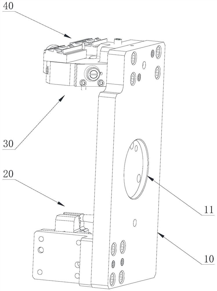
[0049] refer to figure 1 with Figure 4, The base 10 is in the shape of a plate, and a plurality of threaded holes and pin holes are opened on the base 10 to facilitate the connection and fixing of various components. And the bottom surface of the base 10 is also provided with a positioning circular groove 11, and a plurality of fixing holes are provided in the positioning circular groove 11, and the integral fixture can be fixed on the work surface conveniently through the positioning circular groove 11.

[0050] refer to figure 1 with figure 2 , the tenon clamping assembly 20 is arranged on the end of the base 10, including the positioning ball 21 and the tenon seat 22 directly connected to the base 10, ...


PUM


Abstract

The invention discloses a turbine blade sealing tooth machining clamp and a clamping method thereof, and belongs to the technical field of aero-engines. The turbine blade sealing tooth machining clamp comprises a base, a tenon clamping assembly, a blade tip clamping assembly and a blade crown clamping assembly. The tenon clamping assembly is used for clamping the tenon portion of a turbine blade and comprises a positioning ball, a tenon support, a tooth base and a tooth block. The blade tip clamping assembly is used for clamping the blade tip portion, close to a blade crown, of the turbine blade. The blade crown clamping assembly is used for clamping the blade crown portion of the turbine blade. The two ends of the turbine blade are clamped respectively, the blade tip portion close to sealing teeth is fixed, and therefore the system rigidity of a workpiece and the clamp is increased, and the situation that the reject ratio is high due to vibration and deformation generated during machining of the sealing teeth is avoided.

Description

technical field [0001] The invention relates to the technical field of aero-engines, in particular to a machining fixture for sealing teeth of a turbine blade and a clamping method thereof. Background technique [0002] As a key part of an aero-engine, the turbine blade directly affects the performance and safety of the engine, and the requirements for the size and quality of the blade are very strict. A certain type of aero-engine turbine blade is made of nickel-based superalloy investment casting blank, and the complex crown part needs to be machined. The low-pressure turbine blade airfoil profile is ultra-thin and slender and has a difficult-to-machine structure with a special-shaped blade shroud. The special-shaped sealing teeth are circular arc three-tooth thin-wall special-shaped structure, and the minimum thickness of the grate teeth is 1.0mm. The blade has a large twist, and the twist angle of the blade crown is 9 degrees. The special-shaped sealing teeth are proce...

Claims


Application Information

Patent Timeline
Patent Type & Authority Applications(China)
IPC IPC(8): B23Q3/06
CPCB23Q3/062
Inventor 任凤英周林裴聪雷浩强张国君王力文景明辉
Owner AECC AERO SCI & TECH CO LTD
Why Eureka
Try Eureka