Synchronizers for gearshift transmissions

A technology of synchronizing devices and transmissions, applied in clutches, couplings, mechanical drive clutches, etc., to solve problems such as uneven rotation and hum noise

Inactive Publication Date: 2015-12-16
GM GLOBAL TECH OPERATIONS LLC
View PDF7 Cites 2 Cited by
  • Summary
  • Abstract
  • Description
  • Claims
  • Application Information

AI Technical Summary

Problems solved by technology

[0005] Therefore, the technical problem to be solved by the present application is to create a synchronizing device in which the aforementioned disadvantages are overcome and inhomogeneities in the rotation no longer cause disturbing buzzing noises in the transmission

Method used


Image

  • Synchronizers for gearshift transmissions
  • Synchronizers for gearshift transmissions
  • Synchronizers for gearshift transmissions

Examples


Embodiment Construction

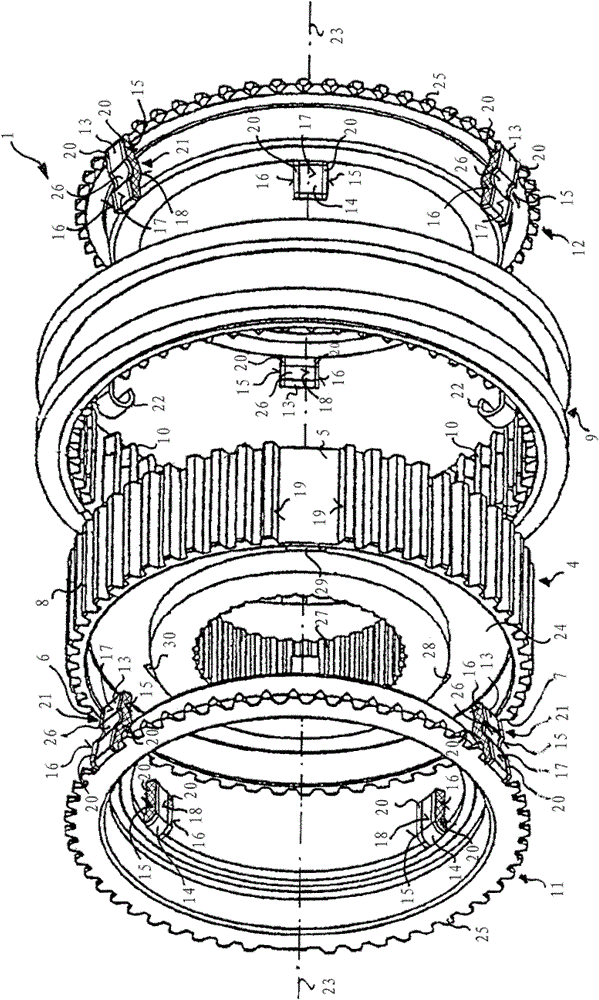
[0019] figure 1 A disassembled schematic three-dimensional schematic sketch of the synchronization device 1 according to the first embodiment of the present application is shown. The synchronizer 1 has four annular components 4 , 9 , 11 and 12 which form a double-acting synchronizer clutch or synchronizer 1 . The synchronizer housing 4 is connected in a rotationally fixed and axially fixed manner to the transmission shaft via a hub part 24 with an internal toothing 27 facing the transmission shaft axis 23 . The synchronizer housing 4 has an external toothing with three recesses 5 , 6 and 7 . The outer protrusions 13 of the synchronizing rings 11 and 12 arranged on both sides of the synchronizer housing 4 engage with the recesses 5 , 6 and 7 in a form-fitting manner.

[0020] Furthermore, in this embodiment of the application, each synchronizing ring 11 and 12 also has an inner projection 14 which engages in a form-fitting manner with corresponding recesses 28 , 29 and 30 in ...


PUM


Abstract

The synchronizing device (1) has a synchronizing body (4), which is fixed on a gearbox shaft in a torque-proof manner and has external teeth (8). A sliding sleeve (9) has inner teeth (10) and is coupled with a toothed gear. A synchronizing ring (11,12) is provided with one or multiple axially aligned lugs, which have radial and axial metallic outer surfaces (15,16,17,18). The radial outer surfaces have a damping coating (20), which has a plastic coating, elastomer, polytetrafluoroethylene, polyamide, particularly polyamide 66 and polyphthalamide.

Description

technical field [0001] The invention relates to a synchronizing device for a gearshift transmission, comprising a synchronizer housing and a sliding sleeve and at least one synchronizing ring, wherein the synchronizer housing is fixed in a rotationally fixed and axially fixed manner on the transmission shaft, and the synchronizer The housing has an external toothing provided with one or more recesses. A sliding sleeve with an internal toothing is arranged axially displaceable on the external toothing and can be coupled to the gearwheel. Furthermore, the synchronization device has at least one synchronization ring which has one or more axially aligned projections. The protrusion extends into the recess. Background technique [0002] A synchronizing device of this type of shift transmission is known from patent document DE 10 2006 060 534 A1 and is usually arranged on the central transmission shaft in manual or automatic shift transmissions, wherein the synchronizer housing ...

Claims


Application Information

Patent Timeline
Patent Type & Authority Patents(China)
IPC IPC(8): F16D23/04F16D23/08
CPCF16D23/025F16D23/06F16D2023/0631F16D2300/10
Inventor 托马斯.霍夫曼
Owner GM GLOBAL TECH OPERATIONS LLC
Why Eureka
Try Eureka