Novel high-power 3D printing cutting machine for steel structure

A 3D printing, steel structure technology, applied in the direction of large fixed members, metal processing machinery parts, maintenance and safety accessories, etc., can solve the problems that are only suitable for steel production lines, not suitable for steel cutting, high price, and reduce vibration and shaking, avoid unstable connection, increase the effect of processing cost

Inactive Publication Date: 2018-04-27
HKUST TIANGONG INTELLIGENT EQUIP TECH (TIANJIN) CO LTD
View PDF1 Cites 3 Cited by
  • Summary
  • Abstract
  • Description
  • Claims
  • Application Information

AI Technical Summary

Problems solved by technology

[0002] The steel structure is a structure composed of steel materials, which is one of the main types of building structures. The structure is mainly composed of steel beams, steel columns, steel work frames and other components made of section steel and steel plates. Welding seam, bolt or nail connection, because of its light weight and simple construction, it is widely used in large factories, venues, super high-rises and other fields. The existing steel cutting machine is easy to operate, can realize automatic control, and can improve steel processing. production efficiency, but the existing steel cutting machine has the disadvantages of large volume and high price. This steel cutting machine is only suitable for steel production lines and is not suitable for cutting steel on site during construction. In the prior art Among them, for example, the invention patent with the application number 201621343302.X includes a body, the top of the inner wall of the body is symmetrically fixedly connected with a motor, the bottom of the output shaft of the motor is fixedly connected with a gear, and the rear side of the inner wall of the body is symmetrically fixedly connected with a The second slide rail, the front surface of the first slide rail is slidably connected with a tooth plate, and when the end of the tooth plate far away from the inner wall of the body is fixedly connected with the first fixed block, the bottom of the first fixed block and the inner wall of the body The bottom of the second fixed block is slidingly connected, the top of the second fixed block is fixedly connected with a first connecting rod, the top of the first connecting rod penetrates to the top of the body, and the second connecting rod is fixedly connected to the left side of the top end of the body There is a connecting block, the end of the connecting block far away from the first connecting rod is movably connected to the second connecting rod through the rotating shaft, the end of the second connecting rod far away from the connecting block is fixedly connected with the second fixed block, and the second fixed The top of the block is fixedly connected with a second clamping block, and the two sides of the second clamping block are fixedly connected with a cylinder, and the two ends of the cylinder away from the inner wall of the first clamping block are fixedly connected with a positioning block. The two sides of the positioning block away from the cylinder are fixedly connected with the second clamping block, the top of the body is symmetrically fixedly connected with the second slide rail, the rear side of the top of the body is fixedly connected with the cutting machine body, the right side of the body The side is fixedly connected with a controller, and the controller is electrically connected with the motor and the cylinder. Although the invention has a simple structure, there are many deficiencies and defects. In the existing equipment, the design of the first slide rail and the second slide rail has Defect, the first slide rail is vertically set and cut, so that the iron filings will fall directly on the slide rail, which will easily cause the blockage of the slide rail, so that the fixed block and the clamping block cannot travel on the first slide rail. Similarly, the body is fixed on the second slide rail This situation also exists on the rail. The cutting iron chip directly falls into the slide rail, which will easily cause the blockage of the second slide rail, affecting the movement of the machine body on the second slide rail, and the splash of cutting will easily cause accidental damage to the operator. In these situations, in order to avoid the above-mentioned technical problems, it is necessary to provide a new type of high-power steel structure 3D printing cutting machine to overcome the defects in the prior art

Method used


Image

  • Novel high-power 3D printing cutting machine for steel structure
  • Novel high-power 3D printing cutting machine for steel structure
  • Novel high-power 3D printing cutting machine for steel structure

Examples


Embodiment Construction

[0022] The following will clearly and completely describe the technical solutions in the embodiments of the present invention with reference to the accompanying drawings in the embodiments of the present invention. Obviously, the described embodiments are only some, not all, embodiments of the present invention. Based on the embodiments of the present invention, all other embodiments obtained by persons of ordinary skill in the art without making creative efforts belong to the protection scope of the present invention.

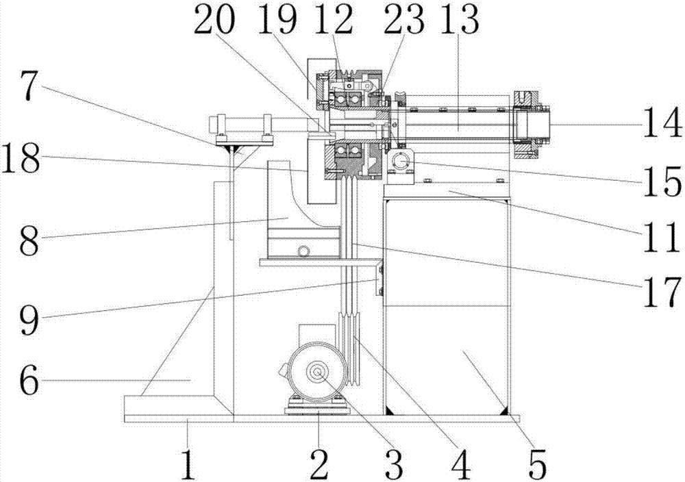
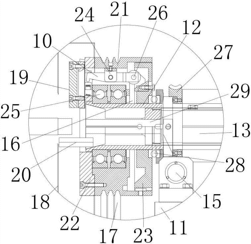
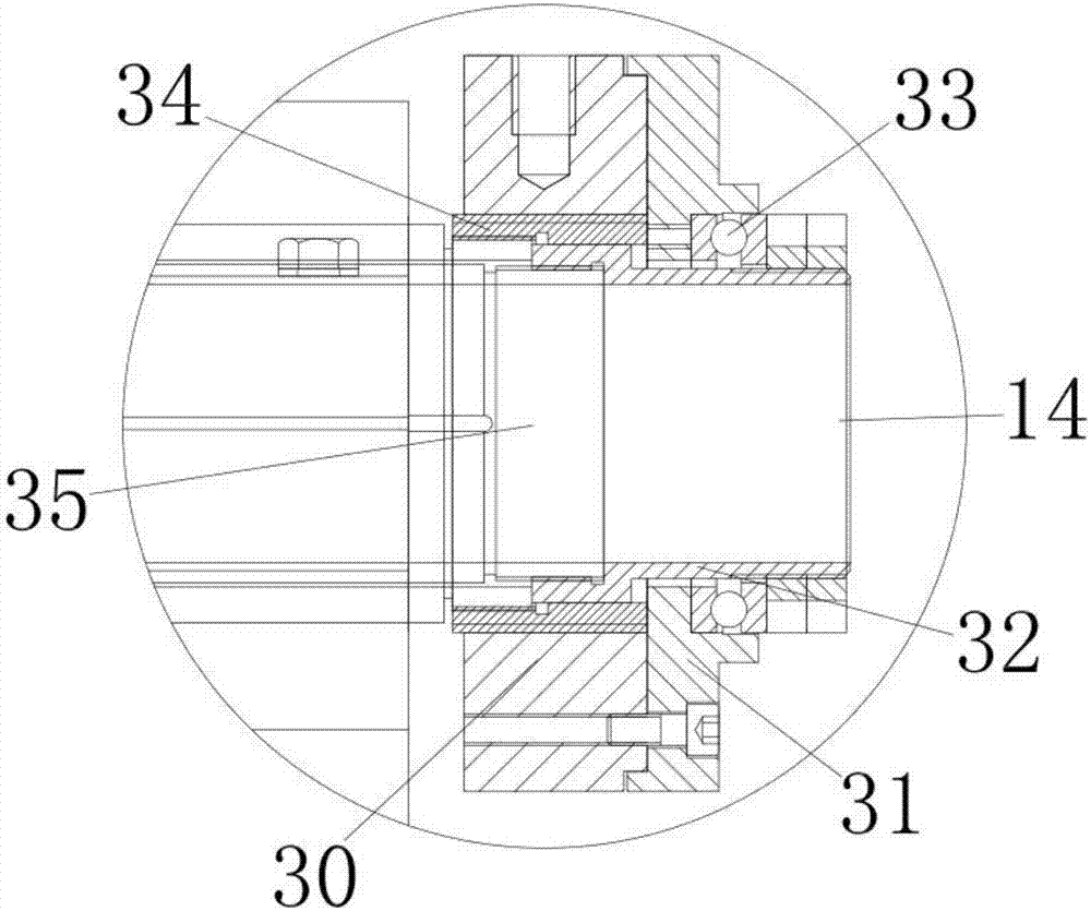
[0023] see Figure 1-3, the present invention provides a technical solution: a new type of high-power steel structure 3D printing cutting machine, including a body 1, the body 1 is made of stainless steel, and is used to install various internal parts, and the left outer wall of the body 1 is equipped with a triangular plate 6 , the triangular plate 6 is made of stainless steel, and is used to make the connection between the bracket 7 and the body 1 more firm....


PUM


Abstract

The invention discloses a novel 3D printing and cutting machine for high-power steel structure, which includes a body, the upper surface of the body is provided with a motor, the lower surface of the motor is connected with the upper surface of the body, and the outer wall of the motor is installed with The first runner, the inner wall of the first runner is connected with the outer wall of the motor, the outer wall of the right side of the body is equipped with a cabinet, the lower surface of the cabinet is connected with the upper surface of the body, the outer wall of the left side of the body Brackets are installed. This new type of cutting machine for high-power steel structures adjusts the processing speed of the cutting piece to the workpiece through the cooperation between the motor, the first runner, the belt and the second runner, and under the action of the rotating shaft and the rotating rod, preventing machining. When the thickness of the workpiece is large, the speed of the motor can be adjusted to increase the speed of the motor, increase the cutting speed, and improve the processing efficiency, thus overcoming the shortcomings of the traditional steel structure cutting machine, which has poor processing accuracy and cannot adjust the cutting speed. The processing efficiency is improved and the processing cycle is saved.

Description

technical field [0001] The invention relates to the technical field of steel structure processing, in particular to a novel high-power 3D printing and cutting machine for steel structures. Background technique [0002] The steel structure is a structure composed of steel materials, which is one of the main types of building structures. The structure is mainly composed of steel beams, steel columns, steel work frames and other components made of section steel and steel plates. Welding seam, bolt or nail connection, because of its light weight and simple construction, it is widely used in large factories, venues, super high-rises and other fields. The existing steel cutting machine is easy to operate, can realize automatic control, and can improve steel processing. production efficiency, but the existing steel cutting machine has the disadvantages of large volume and high price. This steel cutting machine is only suitable for steel production lines and is not suitable for cutt...

Claims


Application Information

Patent Timeline
Patent Type & Authority Applications(China)
IPC IPC(8): B23D79/00B23Q5/10B23Q11/08B23Q1/26B23B19/02
CPCB23D79/00B23Q1/26B23Q1/70B23Q5/10B23Q11/08
Inventor 张超钱浩马向军程锦泽吕胜雨王鹏翔
Owner HKUST TIANGONG INTELLIGENT EQUIP TECH (TIANJIN) CO LTD
Why Eureka
Try Eureka