Valve driving device and method of engine
A driving device and engine technology, which is applied to valve driving devices, engine components, machines/engines, etc., can solve the problems of adding additional parts and complicated structures, and achieve the effect of reducing fuel consumption, good performance and obvious effect.
- Summary
- Abstract
- Description
- Claims
- Application Information
AI Technical Summary
Problems solved by technology
Method used
Image
Examples
Embodiment 1
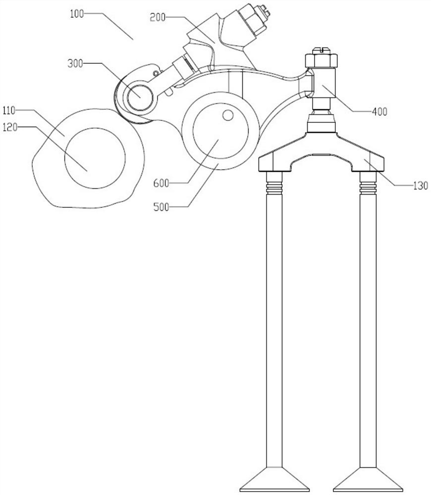
[0056] Such as figure 1 As shown, the engine valve driving device 100 of the present invention is located between the camshaft 120 and the valve part 130, and includes a rocker arm body 500, a drive reset part 200, a roller part 300 and a valve drive part 400; the drive reset part 200, the roller part 300 and valve driving mechanism 400 are installed on the rocker arm main body 500; the rocker arm main body is installed on the rocker arm shaft 600, and the valve driving device 100 rotates around the rocker arm shaft 600; the cam shaft 120 is provided with a cam 110, and the cam 110 Fixed on the camshaft 120 (the center of the camshaft 120 is the center of the cam 110), the cam 110 and the camshaft 120 together rotate around the center of the camshaft 120; the roller part 300 is close to the cam 110 and the camshaft 120, and the valve driving part 400 is close to Valve component 130 .
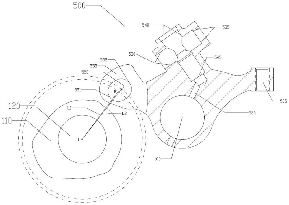
[0057] Such as figure 2 As shown, the rocker arm main body 500 is installed on the rocker...
Embodiment 2
[0068] Embodiment 2 is a modification of Embodiment 1. Such as Figure 10 As shown, the engine valve drive device 1002 of the present invention is located between the camshaft 120 and the valve component 130 , and includes a rocker arm body 5002 , a drive reset component 2002 , a roller component 300 and a valve drive component 400 . The driving reset part 2002 , the roller part 3002 and the valve driving mechanism 400 are installed on the rocker arm main body 5002 , the rocker arm main body 500 is installed on the rocker arm shaft 600 , and the valve driving device 100 rotates around the rocker arm shaft 600 . A cam 110 is arranged on the camshaft 120 , and the cam 110 is fixed on the camshaft 120 (the center of the cam 120 is the center of the cam 110 ). The cam 110 and the camshaft 120 rotate around the center of the camshaft 120 . The roller part 300 is close to the cam 110 and the camshaft 120 , and the valve driving part 400 is close to the valve part 130 .
[0069] Su...
Embodiment 3
[0080] This embodiment is a modification of Embodiment 1. Such as Figure 19 As shown, the engine valve drive device 1001 of the present invention is located between the camshaft 120 and the valve component 130 , and includes a rocker arm body 5001 , a drive reset component 2001 , a roller component 3001 and a valve drive component 400 . The drive reset part 2001 and the valve driving mechanism 400 are installed on the rocker arm main body 5001, and the roller part 3001 is connected together with the rocker arm main body 5001 through the rotating shaft 320 (see Figure 21 ), the rocker arm main body 500 is installed on the rocker arm shaft 600 , and the valve driving device 1001 rotates around the rocker arm shaft 600 . The camshaft 120 is provided with a cam 110 , the cam 110 is fixed on the camshaft 120 (the center of the camshaft is the cam center), and the cam 110 and the camshaft 120 rotate around the center of the camshaft 120 . The roller part 3001 is close to the cam...
PUM
 Abstract
Description
Claims
Application Information
 - R&D
- Intellectual Property
- Life Sciences
- Materials
- Tech Scout
- Unparalleled Data Quality
- Higher Quality Content
- 60% Fewer Hallucinations
Browse by: Latest US Patents, China's latest patents, Technical Efficacy Thesaurus, Application Domain, Technology Topic, Popular Technical Reports.
© 2025 PatSnap. All rights reserved.Legal|Privacy policy|Modern Slavery Act Transparency Statement|Sitemap|About US| Contact US: help@patsnap.com


