
Variable braking force device of high-sensitivity brake

A brake and braking force technology, applied in the direction of brake actuators, gear transmission mechanisms, mechanical equipment, etc., can solve the problems of increasing the manufacturing cost of disc brakes, increasing the weight and layout space of disc brakes, etc. The effects of manufacturing cost and layout space, improved braking force, and simple design structure

Pending Publication Date: 2021-10-08
中实洛阳重型机械有限公司
View PDF6 Cites 0 Cited by
  • Summary
  • Abstract
  • Description
  • Claims
  • Application Information

AI Technical Summary

Problems solved by technology

The main technical problem of the disc brake of the hoist in the prior art is: with the increase of the type of the hoist, for the disc brake of the hoist, it is necessary to increase the corresponding braking force to ensure the braking force of the disc brake. active
At present, in order to increase the braking force of the disc brake, it is necessary to increase the size of the disc spring and the thickness of the disc spring to increase the braking force of the disc brake. This will inevitably increase the weight and layout space of the disc brake, which will inevitably increase the The manufacturing cost of the type brake and the layout space of the brake

Method used


Image

  • Variable braking force device of high-sensitivity brake

Examples


Embodiment Construction

[0019] The specific implementation manners of the present invention will be further described in detail below in conjunction with the accompanying drawings.

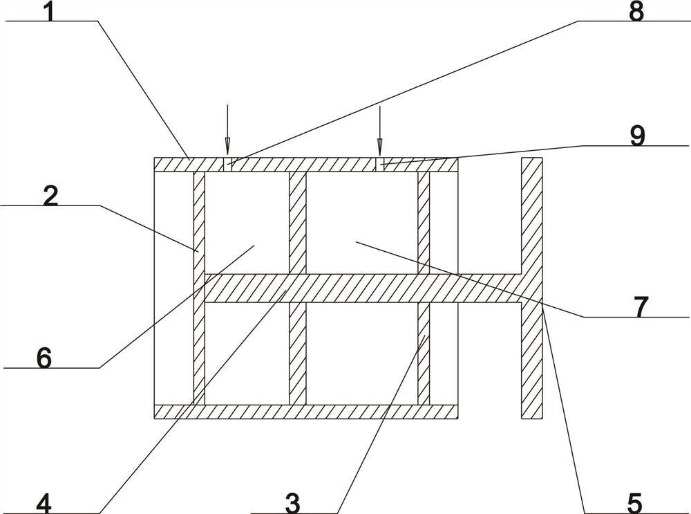
[0020] As shown in the figure, a variable braking force device of a highly sensitive brake includes a brake cylinder 1, a first piston 2, a second piston 3, a brake lever 4, and a brake shoe 5; the brake cylinder 1 is Hollow cylindrical type with both ends closed, the first piston 2 is fixedly arranged in the brake release chamber 5 of the brake cylinder 1, and the second piston 3 is fixedly arranged at the position near the right side of the brake lever 4 The left end of the brake rod 4 is fixedly connected to the middle position on the right side of the first piston 2, and the right end of the brake rod 4 passes through the brake chamber 7 and extends to the outside of the right side of the brake cylinder 1; The moving shoe 5 is fixedly arranged at the right end of the brake lever 4; the brake release chamber 6 is fixe...


PUM


Abstract

The invention belongs to the technical field of driving braking of high-sensitivity brakes, and discloses a variable braking force device of a high-sensitivity brake. A brake cylinder body is a hollow cylinder with two closed ends, a first piston is fixedly arranged in a brake releasing cavity of the brake cylinder body, and a second piston is fixedly arranged at the position, close to the right side, of a brake rod. The left end of the brake rod is fixedly connected with the middle position of the right side of the first piston, and the right end of the brake rod penetrates through a brake cavity and extends out of the right side of the brake cylinder body. A brake shoe is fixedly arranged at the right end of the brake rod. The brake releasing cavity is fixedly formed in the left side of the brake cylinder body, and the brake cavity is fixedly arranged on the right side of the brake releasing cavity. Under the working condition that the size of the brake is not changed, the braking force can be improved, the machining precision of the brake is improved, and the manufacturing cost of the brake is reduced.

Description

technical field [0001] The invention belongs to the technical field of brake driving and braking, and in particular relates to a variable braking force device of a high-sensitivity brake. Background technique [0002] A brake is a device that has the functions of slowing down, stopping or maintaining a stopped state of moving parts (or moving machinery), and is a mechanical part that stops or slows down the moving parts in the machine. For the brake of the hoist, its main function is: when the hoist is not working, use the brake to brake the reel, and at the same time, perform safety braking when the hoist has an emergency accident. [0003] The hoist usually uses a disc brake for braking. When the hoist is started, the hydraulic station outputs pressure oil to open the brake, and the hoist starts to work. When the hydraulic oil is injected into the oil cylinder, the multiple disc springs are pushed by the piston. In the compressed state, when working and braking, the hydra...

Claims


Application Information

Patent Timeline
IPC IPC(8): F16D65/16F16D121/04F16D125/04
CPCF16D65/16F16D2121/04F16D2125/04
Inventor 赵龙王新国周世昌冯博文马鹏涛陈艳红钱峰郭琦李含马乐赵亚松
Owner 中实洛阳重型机械有限公司
Learn More