Safe filling device of filling gun

A technology for filling devices and filling guns, which is applied to equipment loaded into pressure vessels, gas treatment applications, and container discharge methods, etc., and can solve complex power supply methods for gun entry and withdrawal, potential safety hazards, and human intervention control The opening and closing of the three-headed claws and other problems achieve the effect of improving continuous filling ability and easy manipulation

Pending Publication Date: 2021-10-08
CHENGDU ANDERSON MEASUREMENT +1
View PDF1 Cites 0 Cited by
  • Summary
  • Abstract
  • Description
  • Claims
  • Application Information

AI Technical Summary

Problems solved by technology

However, the locking performance of the three-headed claw in this application is unstable, and the three-headed claw cannot securely lock the tip of the liquid-filling gun during the gun feeding process, and it may still fall off, and this application cannot be controlled by human intervention in an emergency The opening and closing of the three-headed claws, the forward and backward switch and the claw opening switch of the claws are integrated together, which is prone to misoperation and causes the claws to open before the pressure relief is completed, which brings potential safety hazards
If the air pressure difference in the inner barrel of the gun barrel cannot be effectively controlled and adjusted, it will easily cause energy waste and excessive loss of instruments, affect the service life of the pneumatic liquid filling gun and bring the safety hazard of the broken gun; further, in this In the application, the efficiency of the power action mode in the liquid filling gun is relatively low, and the power supply method for advancing and withdrawing the gun is relatively complicated, and a large power supply is required during the process of entering the gun, resulting in unnecessary waste of energy. During the process of withdrawing the gun, The piston rod cannot effectively return to the initial position, the barrel cannot remain relatively static, and it is easy to reciprocate automatically under the action of air pressure and compression spring, which is prone to safety hazards of gun collapse during the manual process

Method used


Image

  • Safe filling device of filling gun
  • Safe filling device of filling gun
  • Safe filling device of filling gun

Examples


Embodiment Construction

[0030] The present invention will be described in detail below with reference to the accompanying drawings.

[0031] In order to make the objectives, technical solutions and advantages of the present invention, the present invention will be described in further detail below with reference to the accompanying drawings and examples.

[0032] In this embodiment, the data employed is a preferred embodiment, but is not intended to limit the invention;

[0033] The present invention can achieve a safety filling operation of a spray gun by a plurality of dynamic operations, in this embodiment, the use of low temperature gas is used as the conveying power source.

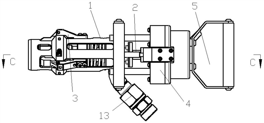
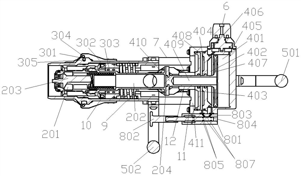
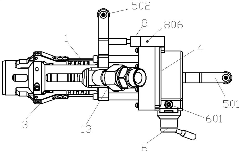
[0034] like Figure 1-4 As shown, this embodiment provides a filling gun safe and raised moving chamber, including inner barrels, outer tubes, clip mechanisms, and handle mechanisms, and the inner barrel is disposed within the outer tube, through the first The compression spring telescopus is relatively slid in the outer gun tub...


PUM


Abstract

The invention discloses a safe filling device of a filling gun. A piston power operation mechanism with double power cylinders and three cavities is adopted to drive an inner gun barrel and an outer gun barrel to do relative reciprocating motion, gun feeding and withdrawing operation of the filling gun is performed in a most reasonable power action mode, further, a clamping mechanism and an air pressure adjusting hole are arranged in a matched mode, clamping jaws of the clamping mechanism and an inner gun barrel head are stably locked, and it is guaranteed that the safety accident of gun collapsing does not occur in the gun feeding and withdrawing processes of the filling gun. According to the safe filling device, the problem that in the prior art, filling and pressure relief operation is achieved in a manual mode is effectively solved, the effect that an advancing and retreating switch of the gun barrels of the filling gun and a jaw opening switch of the clamping jaws are integrated together and do safe filling action is effectively achieved, through the structural design of the filling gun, it is avoided that after the filling gun suddenly loses air source pressure, the potential safety accident caused by gun collapse occurs, and meanwhile, the continuous filling capacity of the power cylinders is improved.

Description

Technical field [0001] The present invention relates to a filling gun safety filling apparatus, which relates to the field of low temperature medium conveying technology. Background technique [0002] The filling gun is one of the core components of the filling system. It is a carrier that enables reliable connection to the car gun and the cylinder to control the flow of the medium to the car cylinder. When adding a gun, add The one-way spool of the nap is open to the one-way spool of the car gun, thereby ensuring that the medium can achieve smooth circulation; when the spray gun is removed from the gun head, the respective one-way spool relies on medium pressure. The action of the spring force is automatically reset (the valve-core seal automatically presses the corresponding inner wall surface) to ensure that the leak is not produced. Before the filling gun is disengaged from the head seat, the remainder between the two spools is discharged through the pressure relief hole of t...

Claims


Application Information

Patent Timeline
Patent Type & Authority Applications(China)
IPC IPC(8): F17C5/02F17C13/00
CPCF17C5/02F17C13/00F17C2270/0168
Inventor 李润黎敏黄波李胜杜菊红魏小清胡健彬陈哲
Owner CHENGDU ANDERSON MEASUREMENT
Why Eureka
Try Eureka