Filling gun capable of achieving safe filling

A filling gun, safe technology, applied in the field of low temperature medium transportation, can solve the problems of excessive loss of instruments, prone to malfunction, complicated power supply methods for feeding and withdrawing guns, etc., to ensure stability, easy control, and continuous improvement. The effect of the ability to raise

Pending Publication Date: 2021-10-08
CHENGDU ANDERSON MEASUREMENT +1
View PDF1 Cites 3 Cited by
  • Summary
  • Abstract
  • Description
  • Claims
  • Application Information

AI Technical Summary

Problems solved by technology

However, the locking performance of the three-headed claws in this application is unstable. The application controls the occlusion of the three-headed claws through an external handle. If the tip of the liquid filling gun is firmly locked, it may fall off, and the application cannot control the opening and closing of the three-headed claw through human intervention in an emergency. The forward and backward switch and the claw opening switch of the claw are integrated together, which is easy Misoperation causes the claws to open before the pressure relief is completed, which brings potential safety hazards
If the air pressure difference in the inner barrel of the gun barrel cannot be effectively controlled and adjusted, it will easily cause energy waste and excessive loss of instruments, affect the service life of the pneumatic liquid filling gun and bring the safety hazard of the broken gun; further, in this In the application, the efficiency of the power action mode in the liquid filling gun is relatively low, and the power supply method for advancing and withdrawing the gun is relatively complicated, and a large power supply is required during the process of entering the gun, resulting in unnecessary waste of energy. During the process of withdrawing the gun, The piston rod cannot effectively return to the initial position, the barrel cannot remain relatively static, and it is easy to reciprocate automatically under the action of air pressure and compression spring, which is prone to safety hazards of gun collapse during the manual process

Method used


Image

  • Filling gun capable of achieving safe filling
  • Filling gun capable of achieving safe filling
  • Filling gun capable of achieving safe filling

Examples


Embodiment Construction

[0033] Below in conjunction with accompanying drawing, the present invention is described in detail.

[0034] In order to make the object, technical solution and advantages of the present invention clearer, the present invention will be further described in detail below in conjunction with the accompanying drawings and embodiments.

[0035] In this embodiment, the data used is the preferred solution, but is not intended to limit the present invention;

[0036] The present invention can realize the safe filling action of the filling gun through various power action modes. In this embodiment, low-temperature gas is used as the transmission power source to illustrate this embodiment. In this embodiment, the pressure of the driving gas source is 0.3MPa-0.8 MPa.

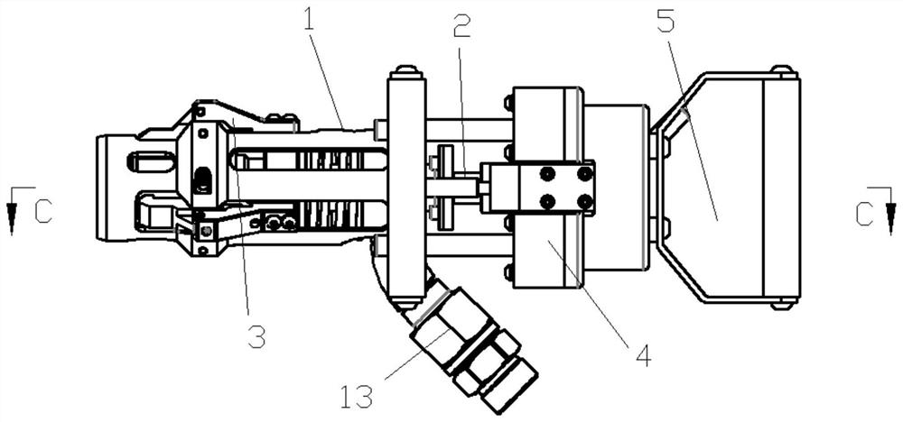
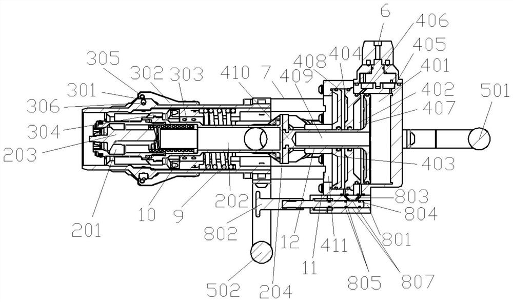
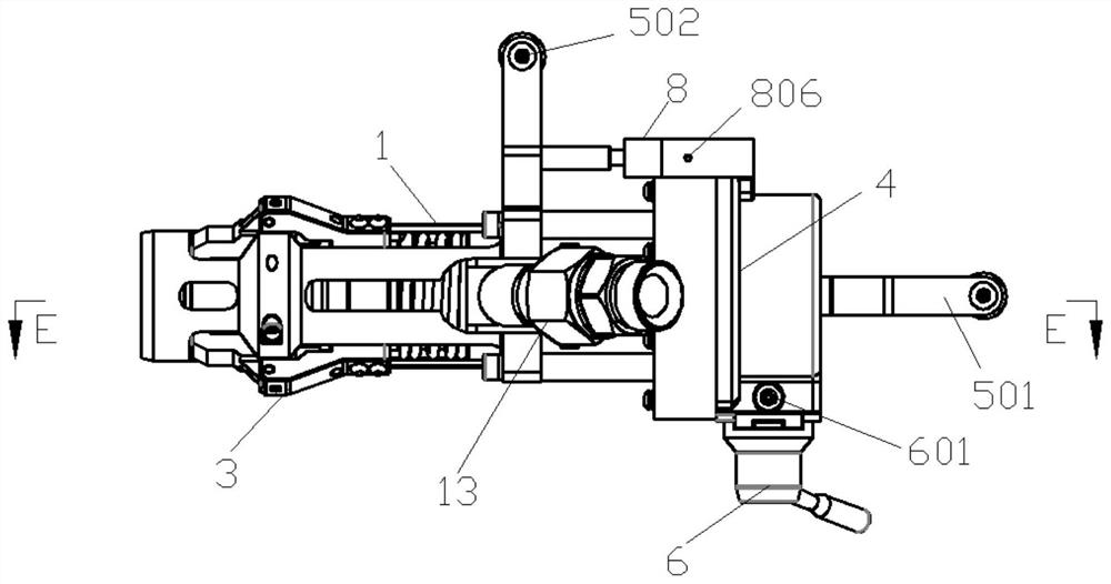
[0037] Such as Figure 1-5 As shown, this embodiment provides a filling gun for safe filling, including an inner gun barrel, an outer gun barrel, a clamping mechanism, a power chamber and a handle mechanism, the inner g...


PUM


Abstract

The invention discloses a filling gun capable of achieving safe filling. The filling gun adopts a piston power operation mechanism with double power cylinders and three cavities to drive an inner gun barrel and an outer gun barrel to do relative reciprocating motion, gun feeding and gun withdrawing operation of the filling gun is executed in a most reasonable pneumatic action mode, and further, a clamping mechanism and an air pressure adjusting hole are arranged in a matched mode, a power source pressure intensity adjusting control valve and the locking structure of the clamping mechanism enable clamping jaws of the clamping structure and an inner gun barrel gun head to be stably locked in the gun feeding action process of the filling gun, it is guaranteed that the safety accident of gun collapse does not occur in the gun feeding and withdrawing processes of the filling gun, and the continuous filling capacity of the power cylinders is improved.

Description

technical field [0001] The invention relates to a filling gun for safe filling, and relates to the technical field of low-temperature medium transportation. Background technique [0002] The filling gun is one of the core components of the filling system. It is the carrier that realizes the reliable connection between the liquid filling machine, the vehicle gun seat and the steel cylinder, and is used to control the flow of the medium to the vehicle steel cylinder. When the filling gun is connected, the filling The one-way valve core of the injection gun and the one-way valve core of the vehicle-mounted gun head seat are pushed apart to ensure the smooth flow of the medium; when the filling gun is separated from the gun head seat, the respective one-way valve cores rely on the medium pressure And the effect of spring force to automatically reset (the valve core gasket automatically presses the corresponding inner wall surface) for sealing to ensure no leakage. Before the fi...

Claims


Application Information

Patent Timeline
Patent Type & Authority Applications(China)
IPC IPC(8): F17C5/02F17C13/00
CPCF17C5/02F17C13/00F17C2270/0168
Inventor 黎敏李润曾学兵黄波李胜杜菊红魏小清李小龙
Owner CHENGDU ANDERSON MEASUREMENT
Why Eureka
Try Eureka