
Convenient-to-adjust automatic surface mounting device for electronic component production

An electronic component, automatic patch technology, applied in the direction of electrical components, electrical components, etc., can solve the problems of low production efficiency, occurrence, affecting work efficiency, etc., to achieve the effect of increasing functionality and practicability

Inactive Publication Date: 2021-10-08
于春梅
View PDF0 Cites 1 Cited by
  • Summary
  • Abstract
  • Description
  • Claims
  • Application Information

AI Technical Summary

Problems solved by technology

[0002] Electronic components are the basic elements in electronic circuits, usually individually packaged, and have two or more leads or metal contacts, and the automatic placement machine is a device for high-speed and high-precision placement of components, which is the entire SMI , the most critical and complex equipment in production, but the current automatic placement machine still has certain limitations. For example, the current automatic placement machine can only absorb and drive electronic components of a certain size, so there are certain limitations , if it is a larger electronic component or an electronic component with a smaller size, it cannot be properly transformed according to the actual size and area of ​​the electronic component when adsorbing and moving, and then perform better adsorption, thereby avoiding The electronic components fall, and when the current electronic components are absorbed, it is easy to deviate due to some external factors, which leads to the electronic components not being in the pre-position, which leads to the automatic placement machine not being able to absorb them. As a result, defective products will appear, which will affect work efficiency and cause low production efficiency.

Method used


Image

  • Convenient-to-adjust automatic surface mounting device for electronic component production
  • Convenient-to-adjust automatic surface mounting device for electronic component production
  • Convenient-to-adjust automatic surface mounting device for electronic component production

Examples


Embodiment 1

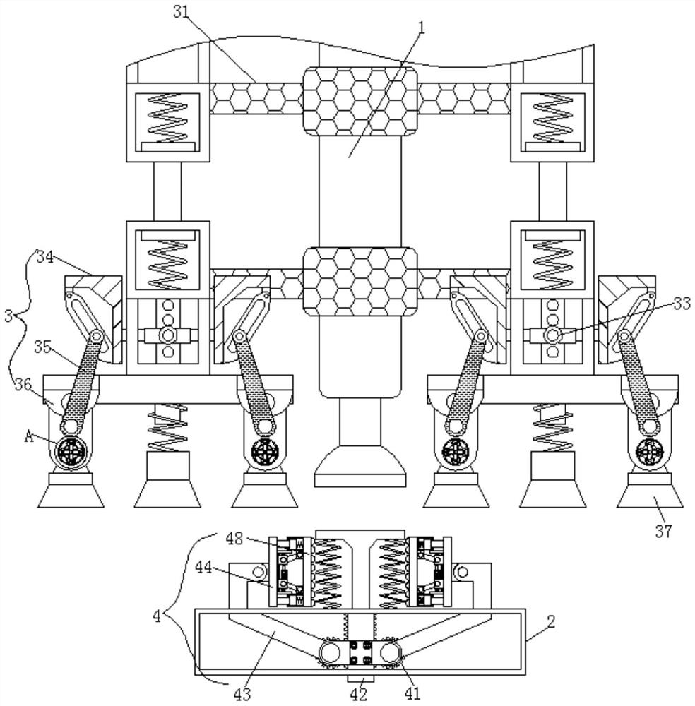
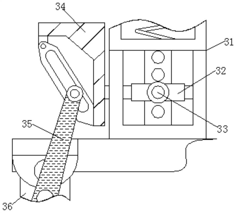
[0026] see Figure 1-3 , a conveniently adjustable automatic placement device for the production of electronic components, comprising a rotating shaft 1 and a platform 2, the surface of the rotating shaft 1 is fixedly connected with an adsorption mechanism 3, the adsorption mechanism 3 includes a turret 31, the left and right sides of the turret 31 are integrally It is set as a telescopic structure to avoid damage to the electronic components when the device absorbs the electronic components. A slide bar is arranged inside the turret 31, and the slide plate 32 slides on its surface, and the slide bar is provided with a hole, and the insertion rod 33 Interlocking with the hole slot, using the snap connection between the hole slot and the insertion rod 33 to control the height of the slide plate 32 sliding on the slide bar, the inside of the turret 31 is slidingly connected with the slide plate 32, and the surface of the slide plate 32 is plugged with a Insert bar 33, the surfac...

Embodiment 2

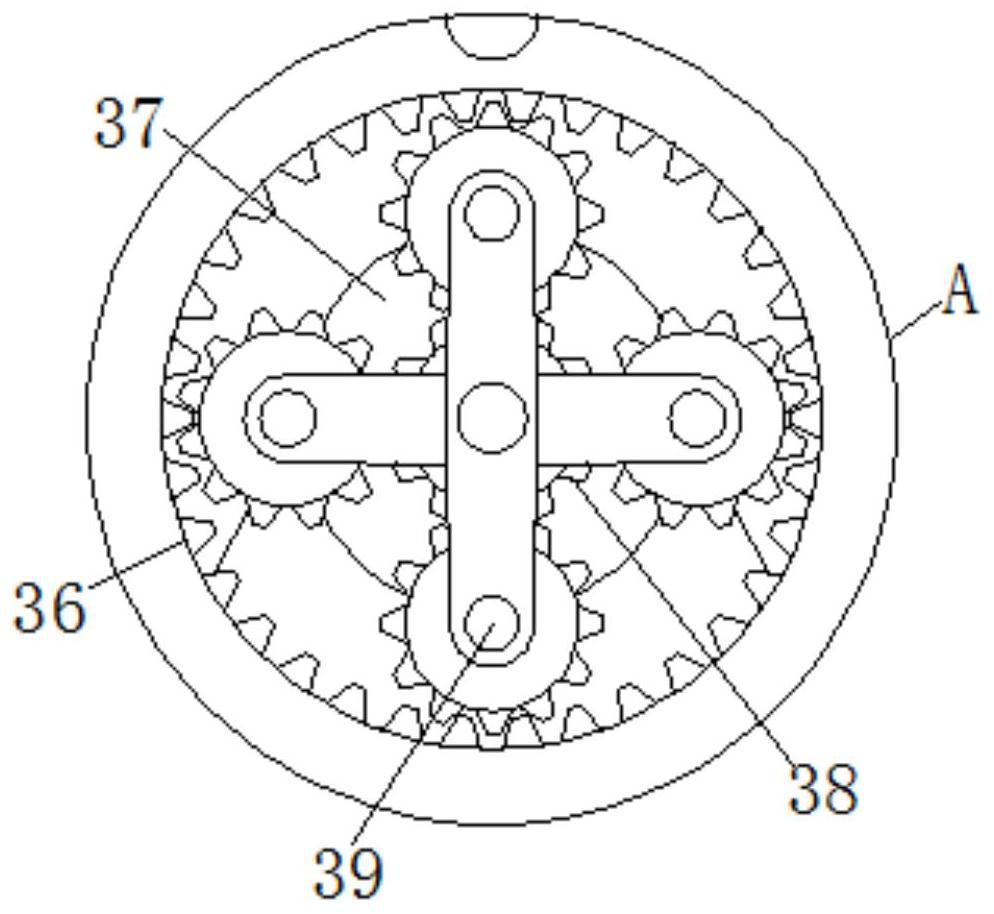
[0028] see figure 1 and Figure 4 , a conveniently adjustable automatic placement device for the production of electronic components, comprising a rotating shaft 1 and a platform 2, the surface of the rotating shaft 1 is fixedly connected with an adsorption mechanism 3, the adsorption mechanism 3 includes a turret 31, and the interior of the turret 31 is slidingly connected with Sliding plate 32, the surface of sliding plate 32 is plugged with insertion rod 33, the surface of sliding plate 32 is fixedly connected with moving block 34, the surface of moving block 34 is slidably connected with connecting rod 35, and the bottom end of turret 31 is fixedly connected with connecting rod 34. Plate 36, the inside of connecting plate 36 is connected with suction cup 37 for rotation, the surface of suction cup 37 is provided with first gear 38, the surface of first gear 38 is connected with rotation tooth 39, and the inside of platform 2 is connected with clamping mechanism 4 for rotat...

Embodiment 3

[0030] see Figure 1-4, a conveniently adjustable automatic placement device for the production of electronic components, comprising a rotating shaft 1 and a platform 2, the surface of the rotating shaft 1 is fixedly connected with an adsorption mechanism 3, the adsorption mechanism 3 includes a turret 31, the left and right sides of the turret 31 are integrally It is set as a telescopic structure to avoid damage to the electronic components when the device absorbs the electronic components. A slide bar is arranged inside the turret 31, and the slide plate 32 slides on its surface, and the slide bar is provided with a hole, and the insertion rod 33 Interlocking with the hole slot, using the snap connection between the hole slot and the insertion rod 33 to control the height of the slide plate 32 sliding on the slide bar, the inside of the turret 31 is slidingly connected with the slide plate 32, and the surface of the slide plate 32 is plugged with a Insert bar 33, the surface...


PUM


Abstract

The invention relates to the technical field of electronic components, and discloses a convenient-to-adjust automatic surface mounting device for electronic component production, which comprises a rotating shaft and a platform, the surface of the rotating shaft is fixedly connected with an adsorption mechanism, the adsorption mechanism comprises a rotating frame, and the interior of the rotating frame is slidably connected with a sliding plate. An inserting rod is inserted into the surface of the sliding plate, a moving block is fixedly connected to the surface of the sliding plate, a connecting rod is slidably connected to the surface of the moving block, a connecting plate is fixedly connected to the bottom end of the rotating frame, a suction cup is rotatably connected to the interior of the connecting plate, and a first gear is arranged on the surface of the suction cup. Through the adsorption mechanism, the adsorption area of the suction cup can be properly adjusted, so that the requirements of electronic elements with different sizes and areas can be met, the electronic elements can be better adsorbed and moved, the manufacturing requirements are better met, and the functionality and practicability of the device are improved.

Description

technical field [0001] The invention relates to the technical field of electronic components, in particular to a conveniently adjustable automatic placement device for the production of electronic components. Background technique [0002] Electronic components are the basic elements in electronic circuits, usually individually packaged, and have two or more leads or metal contacts, and the automatic placement machine is a device for high-speed and high-precision placement of components, which is the entire SMI , the most critical and complex equipment in production, but the current automatic placement machine still has certain limitations. For example, the current automatic placement machine can only absorb and drive electronic components of a certain size, so there are certain limitations , if it is a larger electronic component or an electronic component with a smaller size, it cannot be properly transformed according to the actual size and area of ​​the electronic compone...

Claims


Application Information

Patent Timeline
Patent Type & Authority Applications(China)
IPC IPC(8): H05K13/04H05K13/02
CPCH05K13/0409H05K13/046H05K13/022
Inventor 于春梅梁洲姜明子
Owner 于春梅
Learn More