Tank edge welding structure for full-sealed transformer

A welding structure and transformer technology, applied in the field of power transformers, can solve problems such as poor sealing and oil leakage, and achieve the effects of convenient operation, improved work efficiency and simple structure

Pending Publication Date: 2020-04-14
TIANWEI BAOBIAN HEFEI TRANSFORMER
View PDF0 Cites 1 Cited by
  • Summary
  • Abstract
  • Description
  • Claims
  • Application Information

AI Technical Summary

Problems solved by technology

[0005] The invention provides a box edge welding structure for a fully sealed transformer, which solves the problems of poor sealing and oil leakage

Method used


Image

  • Tank edge welding structure for full-sealed transformer
  • Tank edge welding structure for full-sealed transformer
  • Tank edge welding structure for full-sealed transformer

Examples


no. 1 example

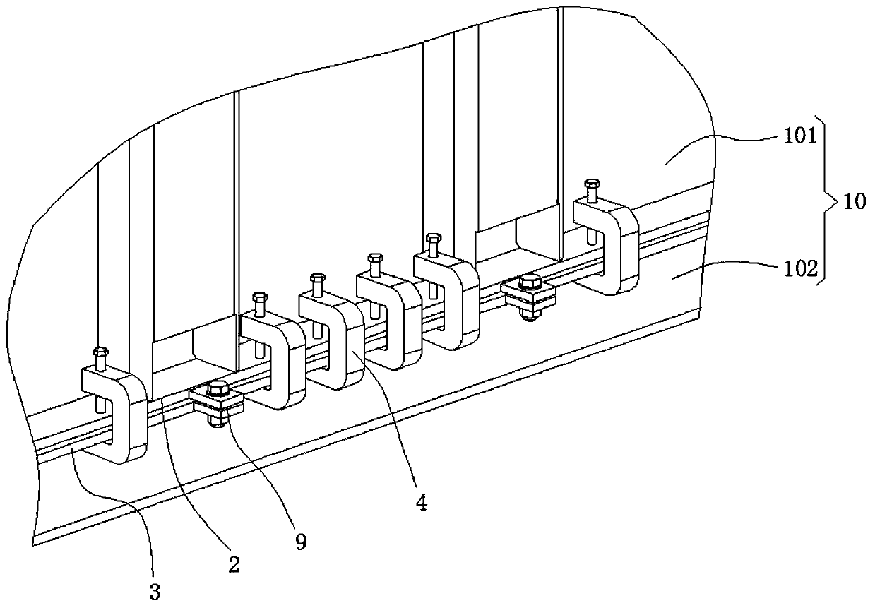
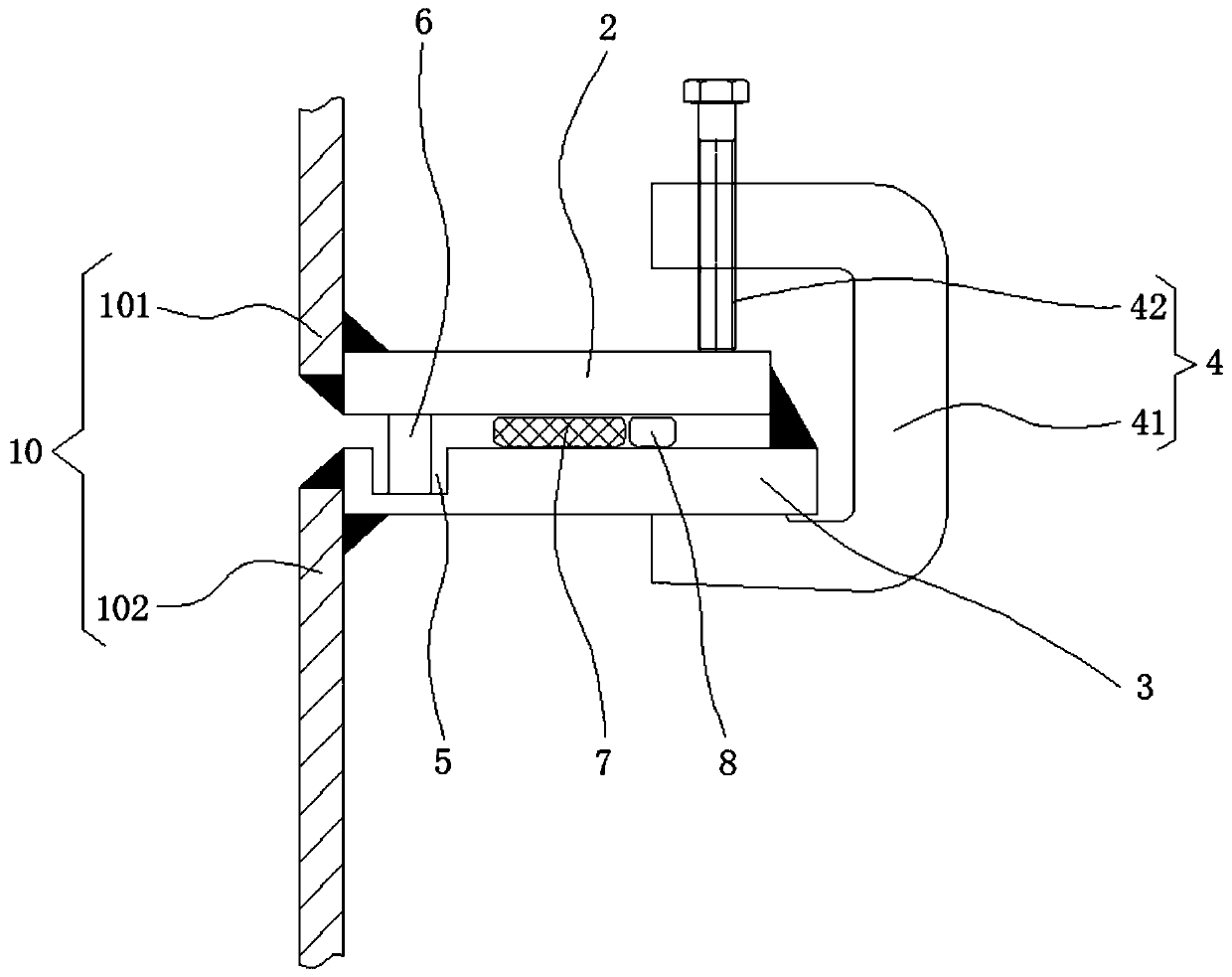
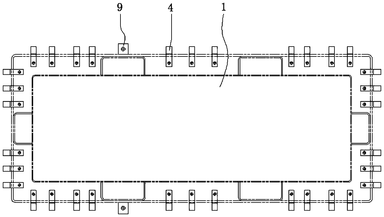
[0035] Please refer to figure 1 , figure 2 and image 3 ,in, figure 1 Schematic diagram of the structure of the first embodiment of the welded structure for the box edge of the hermetic transformer provided by the present invention; figure 2 for figure 1 The combined schematic diagram of the upper box edge and the lower box edge shown; image 3 for figure 1 A top view of the structure of the fuel tank shown. The welded structure of the box edge for hermetically sealed transformers includes:

[0036] Fuel tank 1, described fuel tank 1 comprises upper box body 101 and lower box body 102, and described upper box body 101 is arranged on the top of described lower box body 102, and the outer surface of the bottom of described upper box body 101 is provided with upper box body Along 2, the outer surface of the top of the lower box body 102 is provided with a lower box edge 3;

[0037] A fixture 4, the fixture 4 is arranged between the upper box edge 2 and one side of the l...

no. 2 example

[0063] Please refer to Figure 4 and Figure 5 , based on the tank edge welding structure for a hermetic transformer provided in the first embodiment of the present application, the second embodiment of the present application proposes another tank edge welding structure for a hermetic transformer. The second embodiment is only a preferred mode of the first embodiment, and the implementation of the second embodiment will not affect the independent implementation of the first embodiment.

[0064] Specifically, the difference of the welded structure for the box edge of the fully sealed transformer provided by the second embodiment of the present application is that: it also includes a U-shaped frame 10, and the bottom of the inner wall of the U-shaped frame 10 is provided with an anti-skid block 11 A threaded rod 12 is threadedly connected to the top of the inner wall of the U-shaped frame 10 , and the top end of the threaded rod 12 passes through the U-shaped frame 10 and exte...


PUM


Abstract

The invention provides a tank edge welding structure for a full-sealed transformer. The tank edge welding structure for the fully-sealed transformer comprises an oil tank, the oil tank comprises an upper tank body and a lower tank body, the upper tank body is arranged at the top of the lower tank body, an upper tank edge is arranged on the outer surface of the bottom of the upper tank body, and alower tank edge is arranged on the outer surface of the top of the lower tank body; and a clamp is arranged between one side of the upper tank edge and one side of the lower tank edge. The invention provides the tank edge welding structure for the full-sealed transformer, the reasonable arrangement can be realized according to actual requirements of products; the upper tank edge and the lower tankedge are uniformly stressed; the tank edge welding structure has the advantages of simplifying in-plant operation, reducing manufacturing difficulty of the tank edge welding structure, enabling manufacturing of the fully-sealed transformer to be simpler and more convenient, achieving sealing and positioning through mutual embedding of the upper tank edge and the lower tank edge, meeting requirements of transformer production and manufacturing, being simple in structure and convenient to operate, reducing manufacturing cost and improving working efficiency.

Description

technical field [0001] The invention relates to the field of power transformers, in particular to a box edge welding structure for a fully sealed transformer. Background technique [0002] The shell of large and medium-sized power transformers usually adopts a bell-type oil tank, which is divided into upper and lower sections. The upper section and the lower section are respectively provided with box edges, and the box edges are generally sealed and bolted with rubber gaskets. [0003] During the commissioning and operation of the transformer, affected by the high-energy electromagnetic field, currents will be generated inside the metal parts such as the oil tank. Since the rubber gasket is an insulator, the current between the upper and lower oil tanks flows through the tank along the bolts. When the transformer capacity is large or When the voltage is high, the current will be very large. In severe cases, it will cause the bolts to heat up or sparks will be generated betwe...

Claims


Application Information

Patent Timeline
Patent Type & Authority Applications(China)
IPC IPC(8): H01F27/14
CPCH01F27/14
Inventor 霍建坤夏宏林方囡囡郭永军王丽辉张燕钱秀文靳松
Owner TIANWEI BAOBIAN HEFEI TRANSFORMER
Why Eureka
Try Eureka