Oscillating head mechanism of fiber winding machine

A technology of fiber winding machine and swinging head, which is applied in the field of fiber winding machines, can solve the problems of poor yarn spreading effect and affecting the surface quality of winding products, etc., achieves easier control of glue content and shape and size, and meets the requirements of production of high-voltage insulation products, Obvious effect

Inactive Publication Date: 2007-02-14
HARBIN INST OF TECH
View PDF0 Cites 1 Cited by
  • Summary
  • Abstract
  • Description
  • Claims
  • Application Information

AI Technical Summary

Problems solved by technology

[0003] The object of the present invention is to provide a swing head mechanism of a fiber winding machine, which can solve the problem of existing yarn bundles when multiple yarns are combined into one bundle because the yarn discharge roller adopts a circular structure. It is thick in the middle and thin on both sides, and the yarn spreading effect is not good, so that the surface of the winding product is wavy, which affects the surface quality of the winding product

Method used


Image

  • Oscillating head mechanism of fiber winding machine
  • Oscillating head mechanism of fiber winding machine
  • Oscillating head mechanism of fiber winding machine

Examples


specific Embodiment approach 1

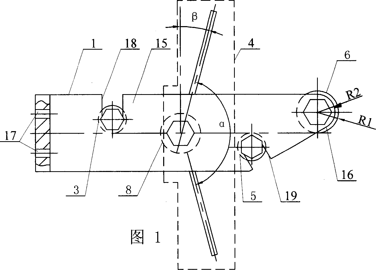
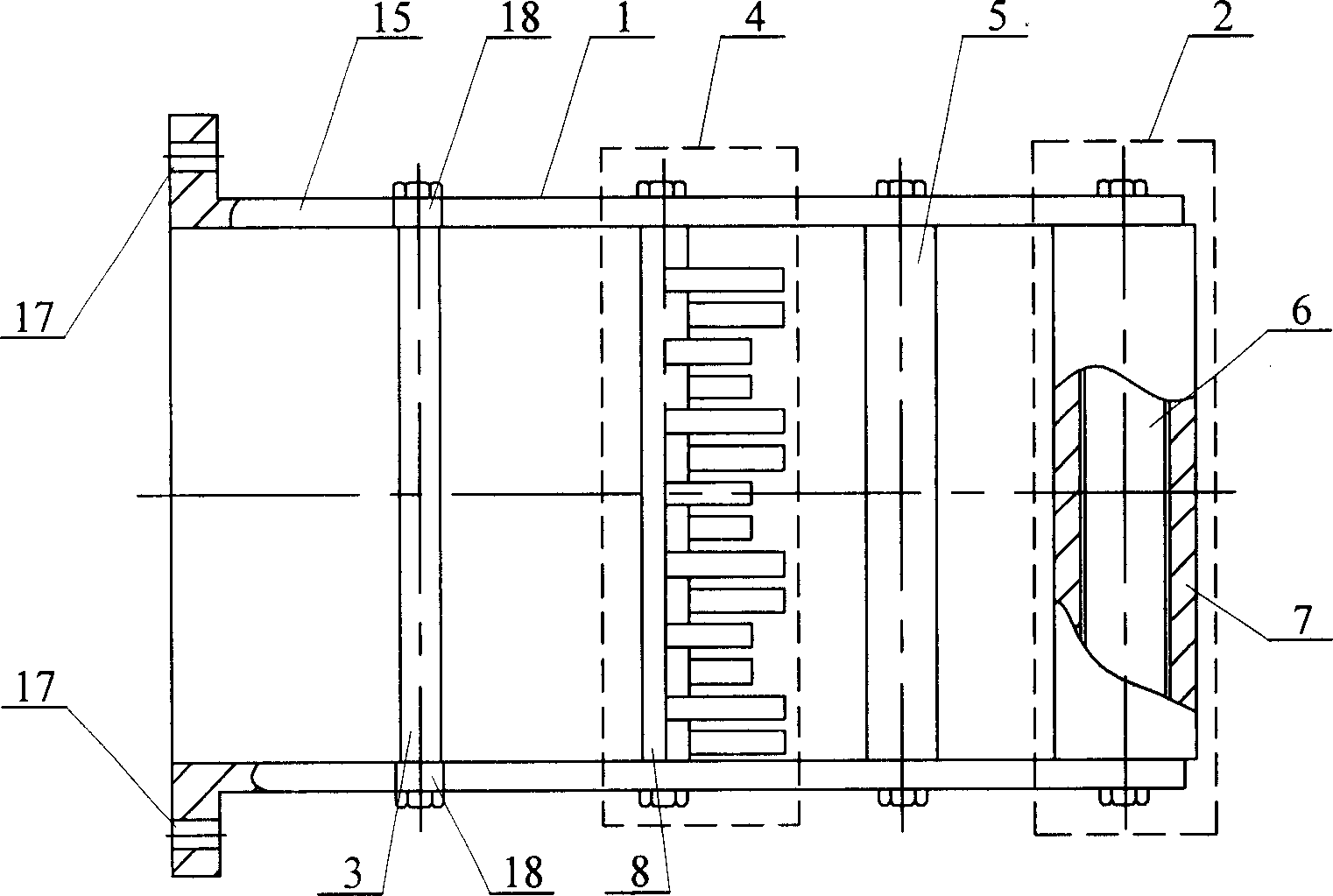
[0007] Specific implementation mode one: in conjunction with Fig. 1~ image 3 Describe this embodiment, this embodiment is made up of bracket 1, yarn discharge roller assembly 2, upper yarn pressing roller 3 that is arranged in bracket 1 and is fixedly connected with bracket 1, yarn dividing roller assembly 4 and lower yarn pressing roller 5 ; The yarn discharge roller assembly 2 is arranged at the yarn outlet end in the support 1, the upper yarn pressing roller 3 is arranged at the yarn inlet end in the support 1, and the yarn dividing roller assembly 4 is arranged at the upper yarn pressing roller 3 and the row Between the yarn roller assembly 2, the lower pressing roller 5 is arranged between the yarn dividing roller assembly 4 and the yarn discharge roller assembly 2; the yarn discharge roller assembly 2 is composed of the yarn discharge roller 6 and the yarn discharge roller 6 and is composed of a yarn-discharging roller sleeve 7 that rotates with the yarn-discharging rol...

specific Embodiment approach 2

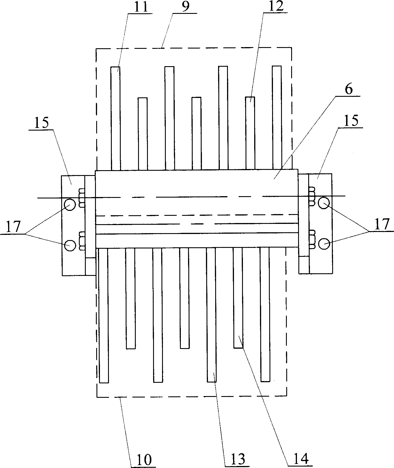
[0008] Specific implementation mode two: in conjunction with Fig. 1~ image 3 Describe this embodiment, the splitting roller assembly 4 of this embodiment is made up of splitting roller 8, upper splitting needle 9 and lower splitting needle 10; A group of upper yarn dividing needles 9 and a group of lower yarn dividing needles 10 arranged equidistantly with the upper yarn dividing needles 9 are fixedly installed equidistantly along the axial direction, and the angle between the upper yarn dividing needles 9 and the lower yarn dividing needles 10 is α is 120°, so that the yarn is staggered up and down. After the yarn is combined on the yarn discharge roller 6, the effect of not leaving the seam and not overlapping can be achieved. The angle β is 30°, which can avoid the defect that the upper and lower yarn-dividing needles rub against the yarn and cause yarn breakage. The upper yarn-dividing needle 9 consists of a group of upper yarn-dividing long needles 11 and a group of The...

specific Embodiment approach 3

[0009] Specific embodiment three: this embodiment is described in conjunction with Fig. 1, the bottom end of the outer wall of the upper yarn pressing roller 3 of the present embodiment and the top end of the outer wall of the yarn dividing roller 8 are on the same plane, and the top end of the outer wall of the lower yarn pressing roller 5 is on the same plane as the yarn discharger. The bottom end of the outer wall of the roller 6 and the horizontal central axis of the spinning roller 8 are on the same plane. Such setting can ensure that the yarns will not leave the seam or overlap after they are combined on the yarn discharge roller, and the flattening effect will be good. Other components and connections are the same as those in the first embodiment.


PUM


Abstract

The present invention relates to fiber winding machine, and is especially the swinging mechanism of fiber winding machine. The present invention includes a yarn arranging roller assembly set on the yarn discharging end on the frame, an upper yarn pressing roller set inside the yarn feeding end of the frame, a yarn separating roller assembly set between the upper yarn pressing roller and the yarn arranging roller assembly, and a lower yarn pressing roller set between the yarn separating roller assembly and the yarn arranging roller assembly. The yarn arranging roller assembly consists of a yarn arranging roller and a yarn arranging roller sleeve set on the yarn arranging roller and rotation fitting with the yarn arranging roller, and the yarn arranging roller has ends fixed to the frame. The present invention has excellent yarn expanding effect, and can meet the requirement of making composite material member in aeronautical and astronautical industry.

Description

technical field [0001] The invention relates to a fiber winding machine. Background technique [0002] The function of the swing head mechanism of the fiber winding machine is to ensure that the multi-ply yarns are combined into one bundle, and are laid flat on the mandrel without separation or overlap. The yarn discharge roller of the swing head mechanism of the existing fiber winding machine adopts a circular structure, the purpose is to make multiple yarns into one bundle, and the yarns do not leave the seam. The disadvantages caused by this are: the yarn bundle is thick in the middle and thin on both sides, and the yarn spreading effect is not good, so that the surface of the wound product is wavy, which brings the following problems to the wound product: 1. When winding, the yarn bundle follows the winding position. Different from the tension of the yarn, the degree of polyyarn is affected, so that the winding thickness changes randomly, so the shape and size of the wi...

Claims


Application Information

Patent Timeline
Patent Type & Authority Applications(China)
IPC IPC(8): B29C70/28B29C70/54B29C70/40
Inventor 韩振宇路华王永章富宏亚韩德东付云忠
Owner HARBIN INST OF TECH
Why Eureka
Try Eureka