Cutting apparatus

A technology of cutting device and camera, applied in fine working devices, parts of grinding machine tools, grinding/polishing equipment, etc., can solve problems such as difficulty in finding bevel cuts, inability to properly detect incision offset, etc., and achieve reliable shooting. Effect

Pending Publication Date: 2021-10-12
DISCO CORP
View PDF1 Cites 0 Cited by
  • Summary
  • Abstract
  • Description
  • Claims
  • Application Information

AI Technical Summary

Problems solved by technology

[0008] However, in the above-mentioned conventional processing device, if there is a positional shift between the imaging area of ​​the upper camera and the imaging area of ​​the lower camera, the deviation between the upper end position of the incision and the lower end position of the incision cannot be detected appropriately.
As a result, chamfers are sometimes difficult to spot

Method used


Image

  • Cutting apparatus
  • Cutting apparatus
  • Cutting apparatus

Examples


Embodiment Construction

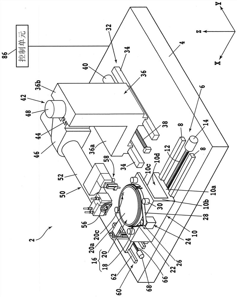
[0027] Hereinafter, embodiments of the present invention will be described with reference to the drawings. figure 1 It is a perspective view showing a configuration example of the cutting device 2 of the present embodiment. In addition, in figure 1 In , some components of the cutting device 2 are represented by functional blocks. In addition, the X-axis direction (machining feed direction), the Y-axis direction (index feed direction), and the Z-axis direction (vertical direction) used in the following description are perpendicular to each other.

[0028] like figure 1 As shown, the cutting device 2 has a base 4 that supports each component. A ball screw type X-axis moving mechanism (first feed mechanism, machining feed mechanism) 6 is arranged on the upper surface of the base 4 . The X-axis moving mechanism 6 includes, for example, a pair of X-axis guide rails 8 fixed to the upper surface of the base 4 and substantially parallel to the X-axis direction. The X-axis moving ...


PUM


Abstract

The present invention provides a cutting apparatus in which a region imaged by one of two cameras can be securely imaged by the other of the two cameras. The cutting apparatus includes a table that includes a support plate transparent in a visible region and supports a workpiece by the support plate; a cutting unit that cuts the workpiece supported by the table; a first feeding mechanism that includes a first moving section for supporting the table and a first motor for moving the first moving section in an X-axis direction; a second feeding mechanism that includes a second moving section for supporting the cutting unit and a second motor for moving the second moving section in a Y-axis direction; a first camera that is disposed on a side of a first surface supporting the workpiece of the support plate; a second camera that is disposed on a side of a second surface opposite to the first surface of the support plate; and a storage section that stores positional deviation amounts in the X-axis direction and the Y-axis direction between an imaging region at a reference position of the first camera and an imaging region at a reference position of the second camera.

Description

technical field [0001] The present invention relates to a cutting device used when machining a plate-shaped workpiece. Background technique [0002] When dividing a plate-shaped workpiece represented by a semiconductor wafer into a plurality of chips, for example, a cutting device equipped with a ring-shaped cutting blade is used. By moving the cutting blade relative to the workpiece while cutting the cutting blade rotating at high speed into the workpiece, the workpiece can be processed (cut) along the moving path and divided into a plurality of chips. [0003] In the above-mentioned cutting apparatuses, an upper camera often captures an image of a workpiece before machining by photographing it. Based on the acquired image, the positional relationship between the table supporting the workpiece and the cutting tool is adjusted, whereby the cutting tool can be properly cut into the planned machining line (lane) set on the workpiece. [0004] This camera is also used, for ex...

Claims


Application Information

Patent Timeline
Patent Type & Authority Applications(China)
IPC IPC(8): B28D5/00B28D5/02
CPCB28D5/022B28D5/0058B28D5/0064H01L21/67092H01L21/681B24B49/12B24B9/065H01L21/67259H01L21/67288H01L21/68764
Inventor 小岛芳昌名嘉真惇花岛聪
Owner DISCO CORP
Why Eureka
Try Eureka