
High and large point column in-situ collapse stoping method

A point-pillar and in-situ technology, applied in ground mining, underground mining, mining equipment, etc., can solve problems such as low recovery rate of mining pillars, work in empty areas, poor safety, etc., and achieve low comprehensive cost of mining and reduce losses Effect of waste and safety improvement

Active Publication Date: 2021-10-12
CHINA MINMETALS CHANGSHA MINING RES INST
View PDF5 Cites 1 Cited by
  • Summary
  • Abstract
  • Description
  • Claims
  • Application Information

AI Technical Summary

Problems solved by technology

The recovery rate of mining pillars is low by using the pillar cutting method and the extraction method, and the personnel and equipment enter the empty area to work, which has poor safety and poor adaptability to the recovery of tall and large point pillars; the concrete pillar replacement method first needs to construct artificial concrete pillars, Then carry out mining of ore pillars, the construction efficiency of artificial concrete ore pillars is low, the cost is high, and personnel and equipment need to enter the goaf for operation; Filling, and then mining pillars, this method is safe to operate, but the construction cost of artificial false roads is high and the efficiency is low, and it is difficult and risky to construct artificial false roads in high and large empty areas
The above methods have been applied in practice, but there are problems such as high safety risk, low efficiency and high cost for the recovery of tall and large pillar ore bodies.

Method used


Image

  • High and large point column in-situ collapse stoping method
  • High and large point column in-situ collapse stoping method
  • High and large point column in-situ collapse stoping method

Examples


Embodiment Construction

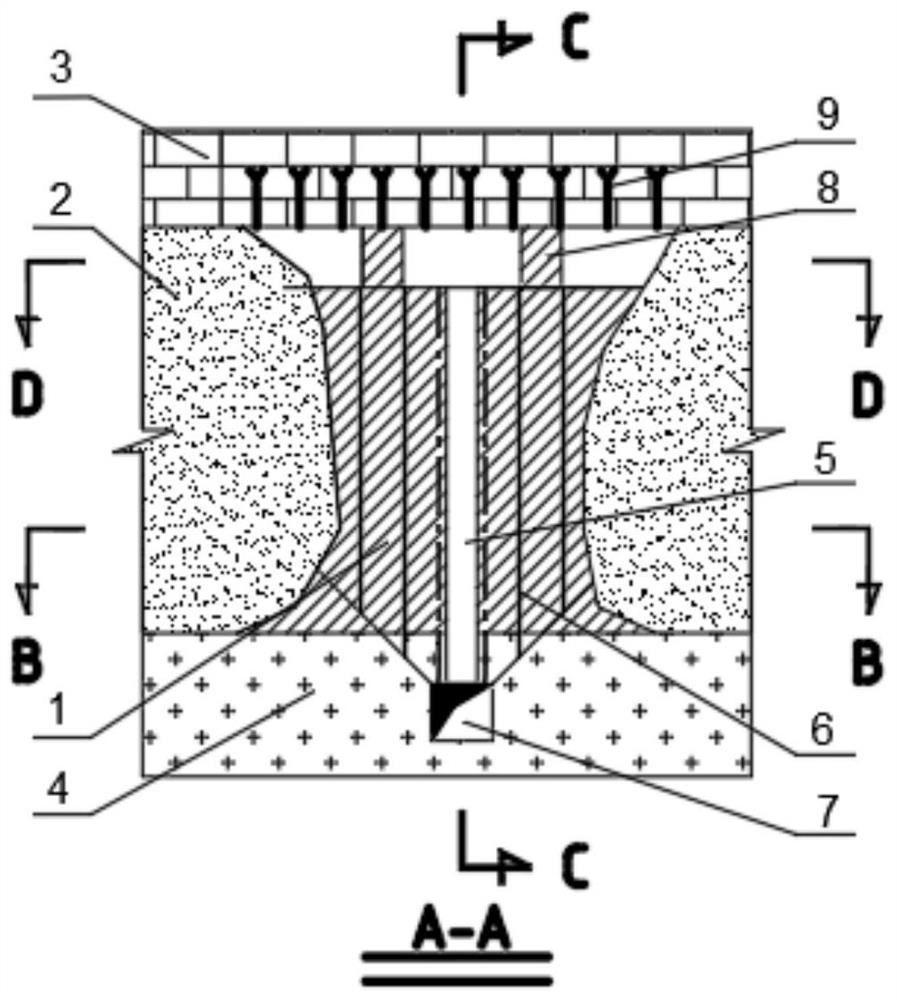
[0030] The technical solutions of the various embodiments of the present invention will be clearly and completely described below in conjunction with the accompanying drawings. Obviously, the described embodiments are only part of the embodiments of the present invention, not all of them; based on the embodiments of the present invention, All other embodiments obtained by persons of ordinary skill in the art without creative efforts fall within the protection scope of the present invention.

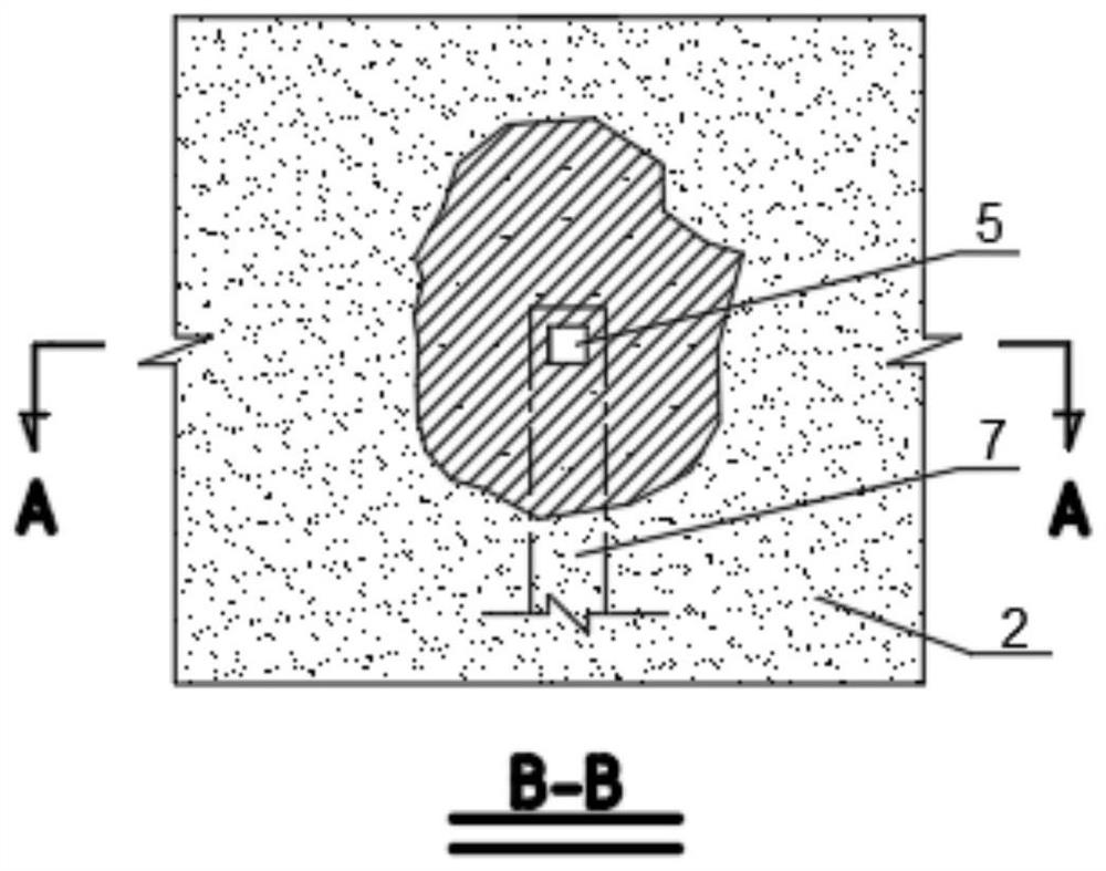
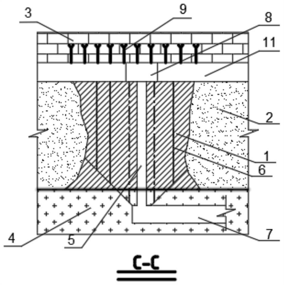
[0031] Such as Figure 1-Figure 4 Shown, adopt a kind of tall point column collapse mining method provided by the present invention in situ, it comprises the following steps:

[0032] Step 1. According to the mine production capacity, filling capacity and recovery period, the occurrence characteristics of the point column and the current engineering status, divide the point column into panels, organize the recovery operation according to the panel, and plan each point in the panel accordi...


PUM


Abstract

The invention discloses a high and large point column in-situ collapse stoping method. The method comprises the following steps that firstly, a goaf is filled twice, an empty roof space is reserved in an empty area during first-time filling, and a filling retaining wall is constructed on a first-time filling body before roof contact during second-time filling so as to form a personnel and equipment access passage; and after the filling body reaches the design strength, a roof cutting space is formed on the upper part of a point column, a panel transportation roadway, an ore removal access path and a cutting raise are constructed in bottom plate rock mass, then downward parallel medium-length blast holes are constructed around the cutting raise in the roof cutting space, the cutting raise serves as a free face, one-time or multi-time blasting ore caving is conducted through millisecond elementary error, an ore removal funnel is formed at the bottom while ore is caved, the caved ore falls into an ore removal access path from the ore removal funnel, ore removal is performed by adopting a carry-scraper matched with a mining truck, and sealing or subsequent filling treatment is performed on the goaf after point-pillar stoping is completed. The method is high in safety, low in engineering construction difficulty, low in cost, high in stoping efficiency and high in ore pillar recovery rate.

Description

technical field [0001] The invention relates to the technical field of mining in underground metal mines, in particular to an in-situ collapse mining method for tall and large point-pillar ore bodies in mines mined by the comprehensive method and the room-and-pillar method. Background technique [0002] In the mines exploited by comprehensive method and room-and-pillar method, a large number of point-pillar ore bodies are often left to control ground pressure and ensure operation safety. Most point-pillar ore bodies have high grade and high economic value. It will cause a waste of resources. However, point pillar mining has great technical and economic difficulties. At present, point pillar mining technologies mainly include: pillar cutting method, extraction method, concrete pillar replacement method, full filling and subsequent mining method, and mining pillars in the empty area surrounded by bagged filling body. method, artificial false road partition filling and mining ...

Claims


Application Information

Patent Timeline
Patent Type & Authority Applications(China)
IPC IPC(8): E21C41/22E21F15/00E21F1/00E21F13/06F42D3/00
CPCE21C41/22E21F15/00E21F1/006E21F13/06F42D3/00
Inventor 孙健曹港欧任泽林卫星周礼朱晨迪
Owner CHINA MINMETALS CHANGSHA MINING RES INST
Learn More