
Device for achieving rapid dividing to form dry and wet areas for maintaining interior of liquid conveying pipeline

A technology for conveying pipelines and liquids. It is applied in the direction of pipe components, pipes/pipe joints/pipes, mechanical equipment, etc. It can solve problems affecting maintenance efficiency and quality, affecting construction period, and threatening personal safety, etc., so as to improve maintenance work efficiency and Maintenance quality, avoid electric shock accidents, and ensure the effect of maintenance quality

Pending Publication Date: 2021-10-12
ANHUI MASTEEL MINING RESOURCES GRP NANSHAN MINING CO LTD +1
View PDF0 Cites 0 Cited by
  • Summary
  • Abstract
  • Description
  • Claims
  • Application Information

AI Technical Summary

Problems solved by technology

When the conveying medium is mixed with solid and liquid and there are large particles such as sedimented sand and gravel at the bottom of the pipeline, the liquid will seep out from the gap of the sediment, and the interception effect is not good
Manual closure means that workers use sand and rags to block the liquid and slurry in the pipeline before repairing and welding. After a few minutes, the liquid will seep in, and workers have to repeatedly use sand and rags to stop the leak, seriously affecting Maintenance efficiency and quality. If maintenance workers come into contact with the liquid in the pipeline and get wet, electric shock accidents will occur, which seriously threatens personal safety.
There are solid sediment particles in the lower half of the pipeline that transports solid-liquid mixed media, and it takes several hours for the liquid to seep out of the sediment, which seriously affects the construction period

Method used


Image

  • Device for achieving rapid dividing to form dry and wet areas for maintaining interior of liquid conveying pipeline
  • Device for achieving rapid dividing to form dry and wet areas for maintaining interior of liquid conveying pipeline
  • Device for achieving rapid dividing to form dry and wet areas for maintaining interior of liquid conveying pipeline

Examples


Embodiment 1

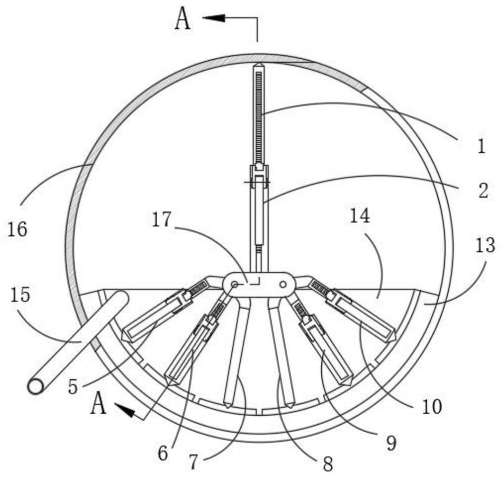
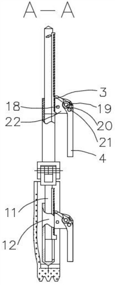
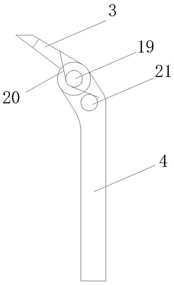
[0027] From Figure 1-3 It can be seen that the device for quickly separating and forming dry and wet areas for internal maintenance of liquid delivery pipelines in this embodiment includes an upper support component, a lower support component and a water retaining component. The upper support component includes an upper support movable ejector rod 1, an upper support fixed Sleeve 2, top tooth 3, handle 4, stop pin 18, top tooth pin 19, butterfly spring 20, handle pin 21 and handle connecting seat 22;

[0028] The upper support movable mandrel 1 is free to expand and contract in the upper support fixed sleeve 2, the upper top of the upper support movable mandrel 1 is processed into a cone, and one side of the upper support movable mandrel 1 is fixedly welded with a rack along the axial direction. The support fixed sleeve 2 is set on the outer surface of the upper support movable mandrel 1, one end of the upper support fixed sleeve 2 is fixedly welded with a connecting seat 17,...


PUM


Abstract

The invention discloses a device for achieving rapid dividing to form dry and wet areas for maintaining the interior of a liquid conveying pipeline, and belongs to the technical field of pipeline maintenance. The device comprises an upper supporting part, a lower supporting part and a water retaining part, the water retaining part is composed of a water retaining sealing strip, a water retaining curtain and an overflow pipe, steel plates are embedded in the edge of the upper portion of the water retaining sealing strip at equal intervals and make contact with a bottom cone of a lower supporting movable ejector rod, the outer edge of the water retaining sealing strip is attached to the pipeline, and the outer side of the water retaining sealing strip is connected with the water retaining curtain. By means of the device, a telescopic adjustable structure is adopted, the device can be suitable for pipelines with various inner diameters, counter-acting force acting on the pipe wall through the upper supporting part is transmitted to the water retaining sealing strip through the lower supporting part, the water retaining sealing strip is extruded to be properly deformed and tightly attached to the inner wall of the pipeline, the effect of cutting off water flow is achieved, dryness of the maintenance areas is kept, the construction maintenance time can be effectively shortened, the maintenance efficiency is improved, the maintenance quality is guaranteed, and the labor intensity of workers is relieved.

Description

technical field [0001] The invention relates to the technical field of pipeline inspection and maintenance, and more specifically relates to a device for forming a dry and wet area by quick partitioning for internal maintenance of a liquid delivery pipeline. Background technique [0002] A large number of pipes are used in industrial production and civil facilities. The materials of the pipes are metal and non-metal, and the transported media are gas, liquid and solid-liquid mixture. Due to the quality problems of the pipeline, the quality of the welding during installation, and the leakage caused by the wear of the conveying medium on the inner wall of the pipeline, the pipeline needs to be replaced and repaired. When replacing the pipeline, when the bottom of the low-lying metal pipeline needs to be repaired by electric welding, there will be a large amount of flowing medium and water mixture in the pipeline continuously flowing to the maintenance site, which seriously aff...

Claims


Application Information

Patent Timeline
Patent Type & Authority Applications(China)
IPC IPC(8): F16L55/136F16L55/07
CPCF16L55/136F16L55/07
Inventor 王勇王玉鼎朱朝伟谭义明龙剑程勇谢洪强
Owner ANHUI MASTEEL MINING RESOURCES GRP NANSHAN MINING CO LTD
Learn More