
Optical water body flow velocity sensor and flow velocity calculation method

A flow velocity sensor and attitude sensor technology, applied in computer control, fluid velocity measurement, velocity/acceleration/shock measurement, etc., can solve problems such as low measurement accuracy, increased rotational resistance, inability to accurately reflect instantaneous flow velocity, etc., and achieve real measurement data , The effect of small fluid resistance

Pending Publication Date: 2021-10-12
SHANDONG UNIV
View PDF6 Cites 0 Cited by
  • Summary
  • Abstract
  • Description
  • Claims
  • Application Information

AI Technical Summary

Problems solved by technology

Disadvantages of mechanical mechanical flow rate sensor: 1. Affected by the inertia of the propeller, it takes a while to start measuring the flow rate, and it cannot accurately reflect the instantaneous flow rate
2. Propeller bearings are corroded due to seawater corrosion for long-term use, increasing rotational resistance and unable to accurately measure flow velocity
3. For the water body or vortex phenomenon with rapidly changing flow direction, it cannot be quickly measured due to the inertia of the cabin and the shroud
Disadvantages of electromagnetic flow rate sensor: 1. The electric potential generated by the flowing water is greatly affected by environmental factors such as temperature and water conductivity, and the measurement accuracy is low.
2. Unable to measure the velocity of fresh water
3. Due to the existence of the coil structure, it has a certain hindering effect on the flow velocity of the surrounding water body, which affects the authenticity of the measurement results
4. For the water body or vortex phenomenon that changes the flow direction rapidly, it cannot be quickly measured due to the inertia of the cabin and the shroud
Acoustic flow velocity sensor: 1. The Doppler effect is greatly affected by environmental factors such as water body temperature, density, and pressure, and the measurement accuracy is low
2. The measurement range of the acoustic flow velocity sensor is limited, and it cannot measure the water velocity in the vicinity of the sensor
3. The acoustic flow velocity sensor can only reflect the macroscopic and rough water flow velocity and flow direction, and cannot accurately and truly reflect the single-point water flow velocity and flow direction
4. Due to the limitation of the measurement mechanism, the acoustic flow rate sensor cannot be measured and calibrated in the existing test pools and tanks
[0006] In summary, the existing water flow velocity sensors can only measure the flow velocity and direction of the water body on a single plane, but cannot measure the flow velocity and direction of the water body in space
Existing water velocity sensors cannot effectively measure water eddies

Method used


Image

  • Optical water body flow velocity sensor and flow velocity calculation method
  • Optical water body flow velocity sensor and flow velocity calculation method
  • Optical water body flow velocity sensor and flow velocity calculation method

Examples


Embodiment Construction

[0039] In order to make the purpose, technical solutions and advantages of the present invention clearer, the following technical solutions in the present invention are clearly and completely described. Obviously, the described embodiments are some embodiments of the present invention, rather than all embodiments. Based on the embodiments of the present invention, all other embodiments obtained by persons of ordinary skill in the art without creative efforts fall within the protection scope of the present invention.

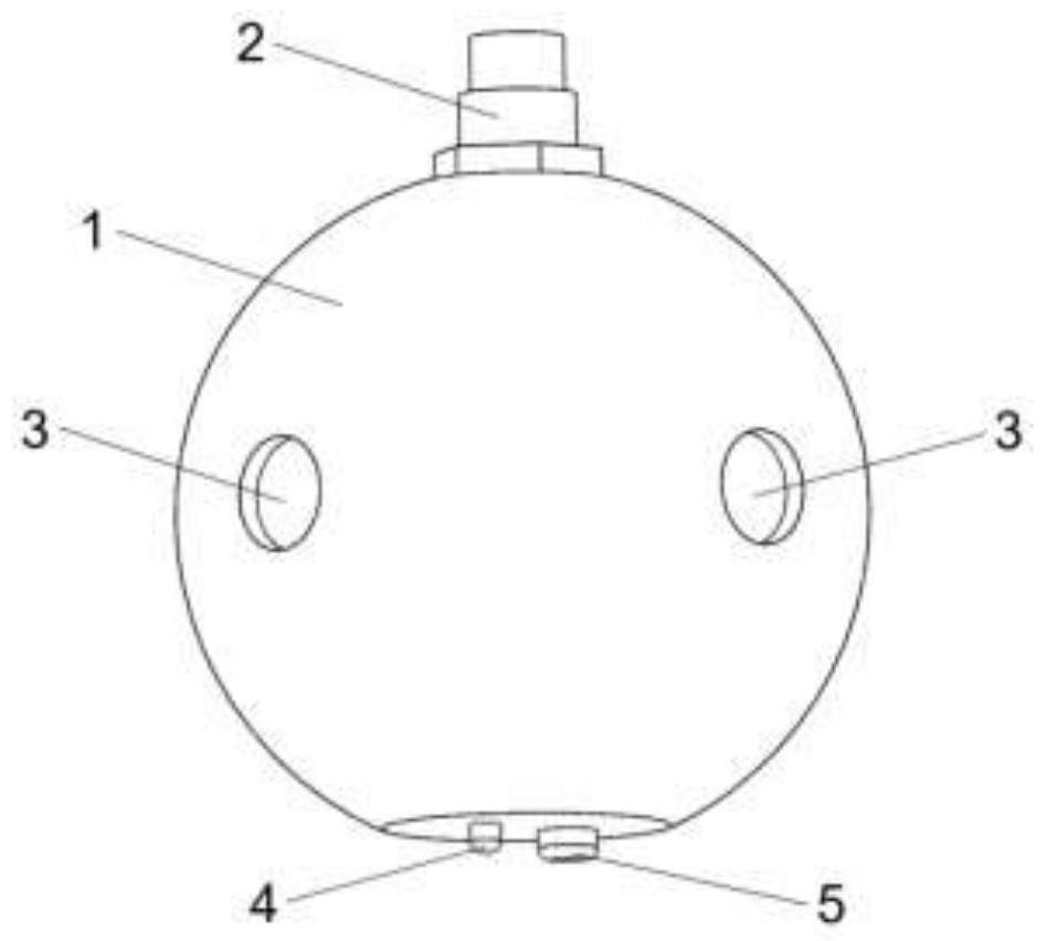
[0040] Such as figure 1 . The present invention provides an optical water flow velocity sensor, comprising a spherical pressure-resistant waterproof cabin 1 made of stainless steel, a watertight connector 2, a transparent optical window 3, a temperature probe 4, and a pressure probe 5.

[0041] The spherical pressure-resistant and waterproof cabin 1 plays the role of waterproof and pressure-resistant protection, and protects the normal operation of the internal o...


PUM


Abstract

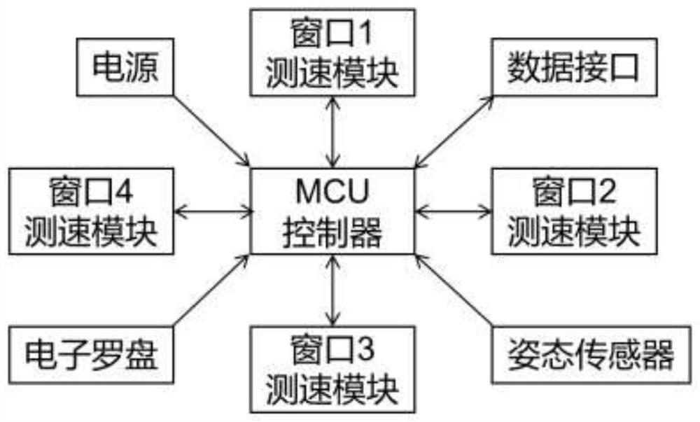
The invention provides an optical water body flow velocity sensor and a flow velocity calculation method. The sensor device comprises a spherical pressure-resistant waterproof cabin; an MCU controller, a power supply, an attitude sensor, an electronic compass and a window velocity measurement module are arranged in the spherical pressure-resistant waterproof cabin in a sealing manner; the attitude sensor, the electronic compass and the window speed measurement module are all connected with the MCU controller, and the power supply supplies power to the MCU controller; the spherical pressure-resistant waterproof cabin is provided with a transparent optical window, and the window speed measurement module is arranged at the position of the transparent optical window. The sensor provided by the invention can directly measure and calculate the real water body flow velocity, is not influenced by environmental factors, can obtain the high-precision water body flow velocity, horizontal plane flow velocity and vertical flow velocity, has small influence on the water body flow velocity around the sensor, and can capture the rapid change of the water body flow direction and capture the small and medium-sized vortex phenomenon.

Description

technical field [0001] The invention relates to the technical field of marine instruments, in particular to an optical water body flow velocity sensor and a flow velocity calculation method. Background technique [0002] Commonly used water velocity sensors are generally divided into mechanical, electromagnetic and acoustic. [0003] The mechanical flow rate sensor is mainly composed of a propeller, a shroud, and a cabin. The flow velocity of the water body is indirectly calculated by measuring the rotation speed of the propeller, and the flow direction of the water body is measured by using the shroud to keep the sensor cabin consistent with the flow direction of the water body. Disadvantages of mechanical mechanical flow rate sensor: 1. Affected by the inertia of the propeller, it takes a while to start measuring the flow rate, and it cannot accurately reflect the instantaneous flow rate. 2. Propeller bearings are corroded due to seawater corrosion for long-term use, inc...

Claims


Application Information

Patent Timeline
Patent Type & Authority Applications(China)
IPC IPC(8): G01P5/26G05B19/042
CPCG01P5/26G05B19/0423
Inventor 王欢齐郝琪贾磊
Owner SHANDONG UNIV
Learn More