[0029] System Embodiment:
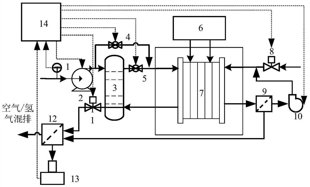
[0030] This embodiment provides a fuel cell shutdown purge system that can be figure 1 The fuel cell stack 7 is purged to take away liquid water from the fuel cell.
[0031] The system includes air paths (including air pipe and outlet air lines) and hydrogen passages (including hydrogen pipelines and hydrogen pipelines).
[0032] like figure 1 As shown, a temperature sensor 1 for detecting the external air is provided at the air opening of the air line, and the probe of the temperature sensor 1 can be disposed inside the line, and the air pressure machine 2 and the first valve are provided on the air line. Switch 4; a throttle 11 and a first water pipe 12 are provided on the air line. The air compressor 2 mates with the throttle 11, which is capable of shutting down the fuel cell-reducing cathode side by providing a certain amount of flow and pressure at the fuel cell system. The first water separator 12 is a gas-liquid separation device, and air and liquid water can be effectively separated.
[0033] A proportional valve 8 is provided on the hydrogen pipeline, and a second water pipe 9 and a hydrogen pump 10 are provided on the hydrogen pipeline. In order to achieve the circulating purge utilization of hydrogen, the position of the second water sewer 9 and the hydrogen pump 10 is set figure 1 As shown, the purged hydrogen is first passed through the second water supply 9, and then the hydrogen pump 10 is passed, and the outlet of the hydrogen pump 10 is directly connected to the hydrogen pipeline. The hydrogen pump 10 is fitted with the proportional valve 8, and the hydrogen gas is provided by providing a flow and pressure to the liquid water on the fuel cell-reducing cathode side by shutting down the fuel cell system. The second water separator 9 is a gas-liquid separation device, and hydrogen and liquid water can be effectively separated.
[0034] The liquid water separated by the first water collector 12 and the second water separator 9 is collected by the liquid collecting device 13. The liquid collecting device 13 can be a lower width, a narrow vessel. And the liquid collecting device 13 is equipped with a liquid level sensor ( figure 1 Not drawn from the actual amount of water brought out with real-time feedback.
[0035] Moreover, the second valve switch 5 and the corresponding line are also provided in this system to match the first valve switch 4 to achieve whether the air discharged from the air compressor 2 is passed by the humidifier 3. The heat sink 6 is dissipated to the fuel cell stack 7 when the fuel cell stack 7 is too high.
[0036] The control device 14 connects the liquid level sensor and the temperature sensor to acquire information acquired by each sensor, and also connect the air compressor 2, the first valve switch 4, the second valve switch 5, the throttle 11, the hydrogen pump 10, and the proportional valve 8, To control these actuators. Moreover, the control device includes a memory and a processor, and the processor is configured to perform instructions stored in the memory to implement a fuel cell shutdown purge method, which combines figure 2 The method will be described in detail.
[0037] First, when the fuel cell system is turned off, the temperature sensor 1 collects the external air temperature T and transmits it to the control device 14, and the control device 14 acquires the power P which is output before the fuel cell system is turned off. The control device 14 calculates the theoretical water content generated in the operation of the fuel cell according to T and P. It should be noted that the power P which is output before the fuel cell system is turned off for the fuel cell system from which the power output is outputted during this time. Among them, how to obtain the theoretical water content generated in the operation of the fuel cell according to P, the principle is that the operating power P in the fuel cell system affects the saturation content of water, according to the calculation of the conventional saturation water content, specifically The author can refer to the author of Hou Xianjun, Du Chuanjin, etc., the design of the vehicle fuel cell engine system design, which is pointed out that according to the design of the electric stack, it can be calculated to obtain H. 2 Quality and O 2Quality, thereby calculating the theoretical water generated by fuel cell work. Moreover, the temperature of the air blown in the air passage and the liquid water brought out after the purge have the following relationship: the lower the air temperature blown in the air path, the more liquid water brought out after the purge. According to this relationship, it is possible to correct the theoretical water generated in the operation of the fuel cell operating in accordance with the power P which is output before the fuel cell system is turned off, so that the theoretical water is more accurate.
[0038] Next, after recording T and P, the control device 14 controls the air path and the hydrogen passage to simultaneously purge at the same time of determining the flow and determination pressure. Among them, for the air passage, the control device 14 controls the opening of the first valve switch 4, controls the closure of the second valve switch 5, the air compressor 2 speed is set to R, the throttle 11 opening degree is set to a, carrying the purge operation of the air path For the hydrogen passage, the rotational speed of the hydrogen pump 10 is provided is R ', and the opening degree of the proportional valve 8 is set to a', and the purge operation of the hydrogen passage is carried out.
[0039] Then, when the air path and the purge operation of the hydrogen passage, the first water water 12 and the second water separator 9 separate the liquid water and collect liquid water by the liquid level collecting device 13. At the same time, the liquid level sensor in the liquid level collecting device 13 collects the current water level in real time, and feeds back to the control device 14.
[0040] Next, the control device 14 calculates the actual water quantity X which is currently purged out based on the liquid level information of the liquid level sensing feedback. The theoretical water amount Y and the actual water amount X, such as x
[0041] Overall, the system develops the purge strategy of the fuel cell system by comparing the theoretical water volume and the actual amount of water, stopping the purge in the actual water volume to the theoretical water, accurately controlling the purge time, and the waterproof sweeping time is too long. Or too short, a good storage environment provides a fuel cell to ensure the service life of the fuel cell. Moreover, the system is used in two types of purge lines, respectively, the hydrogen air path and the air passage, respectively, and the arrangement of the hydrogen air path can prevent toner corrosion.
[0042] In this embodiment, the system uses two types of purge lines to purge the fuel cell. As other embodiments, all the way can be used, for example, only a fuel cell is purged, and the corresponding water separator (gas-liquid separation device) is only set. Moreover, some of the valve switches on the line can be changed according to the requirements. The principle of the corresponding method is unchanged, and both the theoretical water generated in the operation of the fuel cell is increased to the actual water quantity of the purge tape, and the purge is stopped, and it is continuously purged.
[0043] In this embodiment, in order to obtain the actual water quantity X of the purge, a liquid collection device is provided to collect liquid water separated by the divider, and cooperate with the liquid level sensor disposed in the liquid level collection device to obtain the value. As other embodiments, the flow sensor of the liquid water flow can be provided at the outlet of the divider, and the actual water amount X which is blown out can also be calculated from the parameters such as flow and time.
[0044] In this embodiment, in order to obtain the theoretical water amount Y generated in the operation of the fuel cell, it is calculated based on the power P in the external air temperature T and the power P in the operation of the fuel cell. As other embodiments, the theoretical water amount y in the operation of the fuel cell can be calculated only according to the power P in the operation of the fuel cell, thereby speeding up the calculation speed of the theoretical water amount Y. Moreover, existing other methods can also be used to calculate the theoretical water volume Y, which is generated in the operation of the fuel cell. For example, the method of air volume flow, hydrogen volume flow or pressure can be used, and the specific manner is as follows:
[0045] 1) Fuel battery reaction equation: 2h 2 + O 2 = 2h 2 O, increase the air flow meter in the back of the air compressor, measure the flow of air V 1 (L / s), calculate the flow of oxygen based on 21% of the oxygen than air 2 = 0.21 * v 1 , The amount of the material of oxygen in units of time M (o) 2 ) = V 2 / 22.4*32, the amount of material produced in unit time M (H) 2 O) = 2 * m (o 2 ), To obtain the mass M of water generated within the unit time (H 2 O) = 18 * m (h 2 O) According to the density of water and the volume of the water, the volume of water can be obtained.
[0046] 2) According to the hydrogen volume flow or pressure, it can be obtained by using the ideal state equation.
[0047] Method Example:
[0048] This embodiment provides a fuel cell shutdown purge method, such as image 3 As shown, the specific steps include:
[0049] After the fuel cell system is turned off, it is first necessary to calculate the theoretical water generated in the operation of the fuel cell in accordance with the power and the temperature of the external air output in the operation of the fuel cell, and the fuel cell is continuously purged, and then the gas after the purge is carried out. The liquid level obtained by collecting and collecting gas-liquid separation, collecting and collecting gas-liquid separation, to obtain the actual amount of water jet, with the continuous progression of the purge process, the actual amount of water is increasing, and the actual water increases to theory When the water is water, the purge can be stopped to precisely control the purge time, prevent the purge time from being too long or too short.
[0050] When purging the fuel cell, the fuel cell can be continuously purged with the air and air paths, or only the air path is purged. The specific purge method does not limit.
[0051] This method can be applied to system embodiments such as figure 1 In the system shown, accurate control of the purge time is realized to prevent too long or too short. In this system, the fuel cell is continuously purged by two lines, and the hydrogen valve and the throttle are provided on the air path, and a hydrogen pump and a proportional valve are provided on the hydrogen passage. At this time, the air passage can be controlled by control. The air compressor speed, the airway is throttled, the hydrogen pump speed, and the proportional valve opening change the efficiency of the purge.
[0052] Device Embodiment:
[0053] This embodiment provides a fuel cell shutdown purge device, such as Figure 4 As shown, the apparatus includes a memory and a processor, and a bus and an I / O interface, a processor, an I / O interface, and a communication between each other through a bus. The processor can call logic instructions in the memory to perform the following method: After the fuel cell system is turned off, it obtains the theoretical water generated in the operation of the fuel cell; continuously purge the fuel cell, gas-liquid separation of the purge after purge , Collect the actual water volume brought out; compare theoretical water and actual water, until the actual amount of water increases to the theoretical water, stopping the purge.
[0054] The logic instructions in the above memory can be implemented in the form of a software functional unit and as a separate product sales or use, or may be stored in a computer readable storage medium.