Throat pipe type airflow drafting device for production of warm-keeping velvet materials

A drafter and tube-type technology, which is applied in the field of throat-type airflow drafters for the production of thermal fleece, can solve the problems of insufficient drafting strength, reduce product quality, affect the thermal insulation effect of thermal fleece, etc., so as to improve the product. Quality, strength-enhancing effect

Active Publication Date: 2021-10-15
吉祥三宝高科纺织有限公司
View PDF3 Cites 0 Cited by
  • Summary
  • Abstract
  • Description
  • Claims
  • Application Information

AI Technical Summary

Problems solved by technology

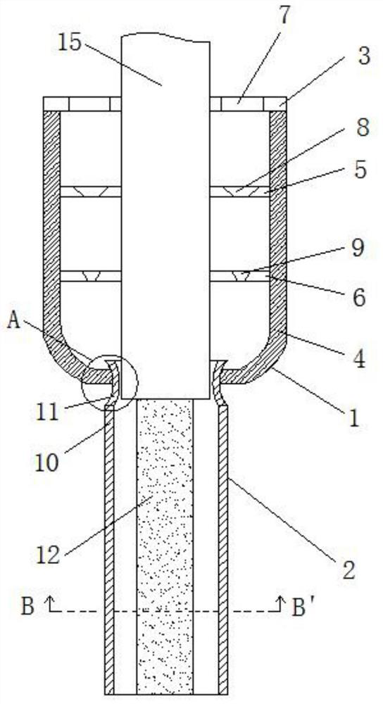
[0003] At present, in the production process of the above-mentioned warm fleece, the air drafter is an important equipment in the production process. The tubular air drafter passes through the gap formed between the drafting cap and the central tube, driven by high-pressure air Negative pressure is used to draw the tow, and it is stretched and thinned under the hot air flow until it breaks, forming chaotically arranged superfine fibers, which fall on the surface of the single-layer fiber web on the conveying curtain of the melt blown equipment, forming a goose down imitation However, the inventor found in actual use that after the fibers are ejected from the porous spinneret, multiple fibers will easily entangle with each other when pulled out, making the fibers difficult to be broken. Or the entanglement of multiple fibers causes the fiber stem to be too large, and at the same time, there is insufficient drafting airflow strength, resulting in insufficient drafting force, which eventually leads to too large fiber stem, which seriously affects the thermal insulation effect of the warm fleece material and reduces product quality. , therefore, the present invention proposes a throat-type air drafter for the production of warm fleece that can solve the above-mentioned problems

Method used


Image

  • Throat pipe type airflow drafting device for production of warm-keeping velvet materials
  • Throat pipe type airflow drafting device for production of warm-keeping velvet materials
  • Throat pipe type airflow drafting device for production of warm-keeping velvet materials

Examples


Embodiment Construction

[0023] The following will clearly and completely describe the technical solutions in the embodiments of the present invention with reference to the accompanying drawings in the embodiments of the present invention. Obviously, the described embodiments are only some, not all, embodiments of the present invention. Based on the embodiments of the present invention, all other embodiments obtained by persons of ordinary skill in the art without making creative efforts belong to the protection scope of the present invention.

[0024] In the description of the present invention, it should be noted that the orientation or positional relationship indicated by the terms "vertical", "upper", "lower", "horizontal" etc. is based on the orientation or positional relationship shown in the drawings, and is only In order to facilitate the description of the present invention and simplify the description, it does not indicate or imply that the device or element referred to must have a specific o...


PUM


Abstract

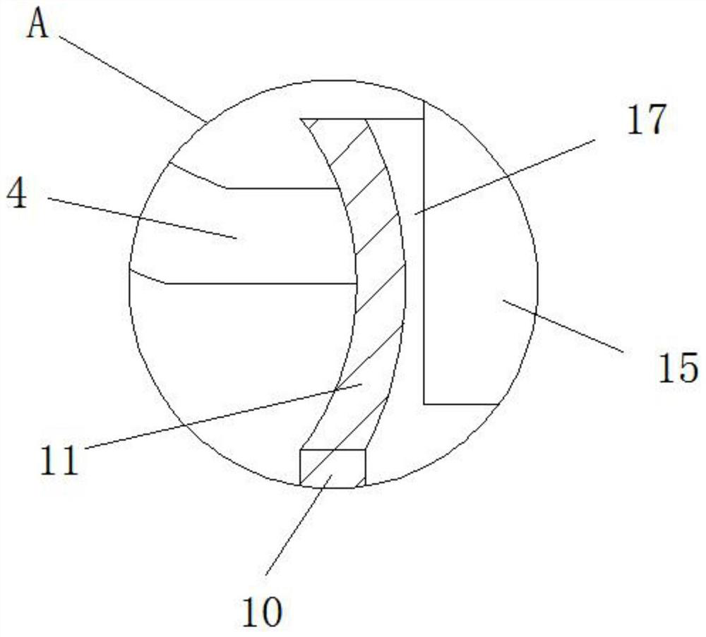
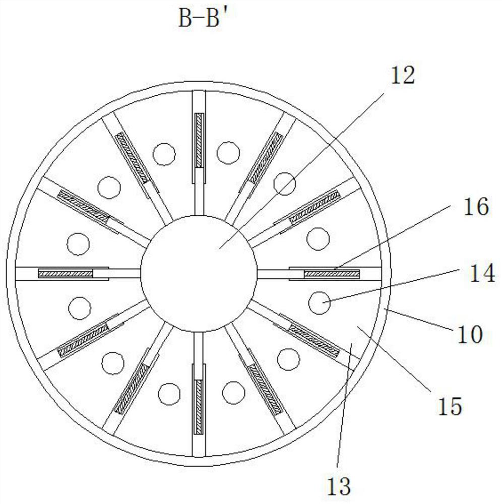
The invention relates to the technical field of warm-keeping velvet material production, in particular to a throat pipe type airflow drafting device for production of warm-keeping velvet materials. The throat pipe type airflow drafting device comprises an airflow pipe and a drafting pipe; the airflow pipe is fixedly arranged outside a spinneret pipe in a sleeving mode; the drafting pipe is fixedly arranged at the lower end of the airflow pipe, and the drafting pipe communicates with the airflow pipe; the airflow pipe comprises an air inlet plate fixedly connected with the spinneret pipe; a pressurizing seat is fixedly mounted at the lower end of the air inlet plate; the drafting pipe comprises a throat pipe located at the top; a drafting sleeve is arranged at the lower end of the throat pipe; a central pipe is arranged in the drafting sleeve; and the lower end of the pressurizing seat is fixedly connected to the outside of the throat pipe in a sleeving manner. Compared with the prior art, the drafting device has the advantages that the fibers pulled out of spinneret orifices can be isolated by partition plates, so that the fibers are synchronously drafted and cannot be mutually entangled and interfered, forming and snapping of the fibers are greatly facilitated, and the product quality is improved.

Description

technical field [0001] The invention relates to the technical field of thermal fleece production, in particular to a throat type air drafter for thermal fleece production. Background technique [0002] Imitation down products (especially imitation goose down) have a potential market. The structure of imitation goose down fiber is made of PET as the down branch and PP as the down branch. The high-speed hot air evenly disperses the short PET fibers with a fineness of 15-50 μm into the air flow field of the melt blown equipment, so that PET and PP are bonded to form a goose down structure. [0003] At present, in the production process of the above-mentioned warm fleece, the air drafter is an important equipment in the production process. The tubular air drafter passes through the gap formed between the drafting cap and the central tube, driven by high-pressure air Negative pressure is used to draw the tow, and it is stretched and thinned under the hot air flow until it breaks...

Claims


Application Information

Patent Timeline
Patent Type & Authority Applications(China)
IPC IPC(8): D01D5/12
CPCD01D5/12Y02P70/62
Inventor 马晓飞张丽张志成
Owner 吉祥三宝高科纺织有限公司
Why Eureka
Try Eureka