Construction Method of Fair-faced Concrete for Special-shaped Curved Surface Beamless Floor Slab
A technology of fair-faced concrete and beamless floor slabs, which is applied to the preparation of floor slabs, formwork/formwork/work frames, and building components on site, and can solve the troublesome problems of applying release agents to formwork
- Summary
- Abstract
- Description
- Claims
- Application Information
AI Technical Summary
Problems solved by technology
Method used
Image
Examples
Embodiment 1
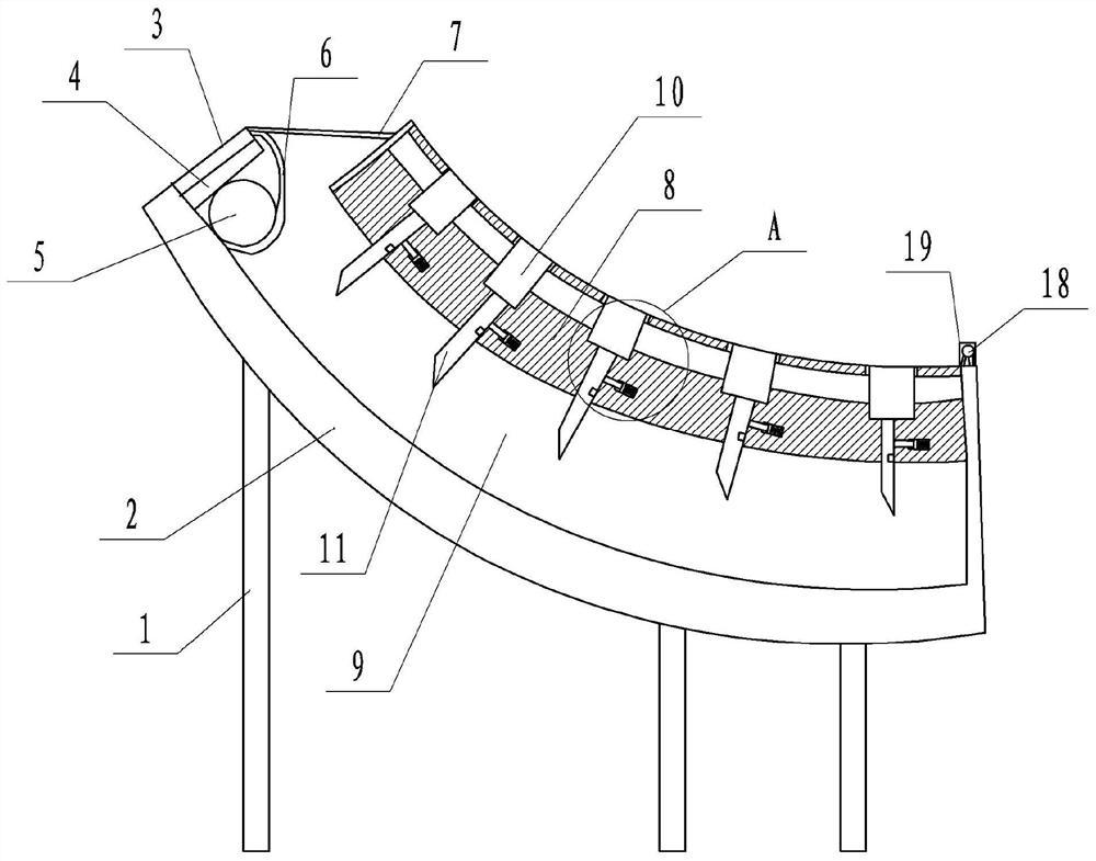
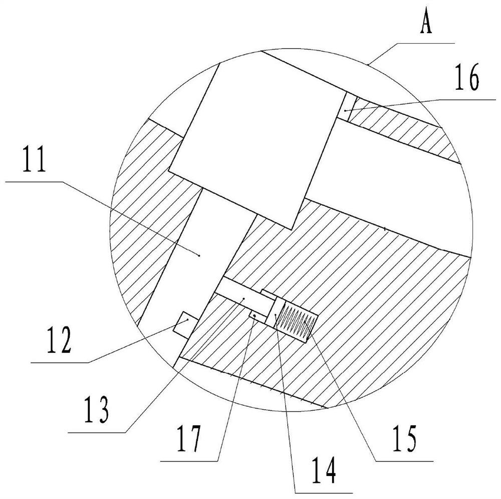
[0020] basically as attached Figure 1-Figure 2 shown.
[0021] The construction method of fair-faced concrete for the beamless floor slab with special-shaped curved surface includes the following steps:
[0022] A. Modeling design, using Auto CAD and Rhino software for simulation design. The bearing capacity calculation is carried out by the safety calculation software of Pinming.
[0023] B. Set out lines, carry out three-dimensional lofting, and use laser points for projection construction. As a result, through the three-dimensional lofting, it is possible to perform fine lofting for the irregularly-shaped curved surface. On the rhino 1:1 three-dimensional solid model, the corresponding elevation of each required node is cut horizontally to form a plan view, the coordinates of the control point are picked up, and a high-precision total station is used for stakeout and control.
[0024] C. Template installation, taking some templates as an example, combined with Figure...
Embodiment 2
[0033] combine figure 1 As shown, a pipe frame 19 is slid on the top of the plate body 8 along the upper surface of the plate body 8. The specific sliding method is as follows: the top of the plate body 8 is provided with a chute, and the pipe frame 19 is welded with a pipe frame 19 located in the chute. slider. The pipe frame 19 is provided with a nozzle 18, and the nozzle 18 is provided with bristles. The bottom of the spray pipe 18 is provided with a liquid outlet hole, and the inside of the spray pipe 18 is provided with a release agent. In this way, in step D, by sliding the pipe rack 19, the pipe rack 19 drives the nozzle 18 to move, and the bristles move on the top of the plate body 8, so that the release agent is brushed on the top of the plate body 8 in a large area, and the operation is simple convenient.
PUM
 Abstract
Description
Claims
Application Information
 - R&D
- Intellectual Property
- Life Sciences
- Materials
- Tech Scout
- Unparalleled Data Quality
- Higher Quality Content
- 60% Fewer Hallucinations
Browse by: Latest US Patents, China's latest patents, Technical Efficacy Thesaurus, Application Domain, Technology Topic, Popular Technical Reports.
© 2025 PatSnap. All rights reserved.Legal|Privacy policy|Modern Slavery Act Transparency Statement|Sitemap|About US| Contact US: help@patsnap.com


