Gas and water composite cooling visual probe structure

A composite cooling and water cooling technology, used in the field of visual probes, can solve the problems of high airflow velocity, cold and hot flow field interference, and high temperature

Inactive Publication Date: 2021-10-15
SICHUAN UNIV +1
View PDF8 Cites 4 Cited by
  • Summary
  • Abstract
  • Description
  • Claims
  • Application Information

AI Technical Summary

Problems solved by technology

Contact measurement methods such as conventional probes and hot-wire anemometers often cause certain disturbances to the measured cold and hot flow fields, and can only obtain local point parameters
At the same time, due to the high temperature and high air velocity in the combustion chamber, the arrangement of probes and hot wires is also very difficult

Method used


Image

  • Gas and water composite cooling visual probe structure
  • Gas and water composite cooling visual probe structure
  • Gas and water composite cooling visual probe structure

Examples


Embodiment 1

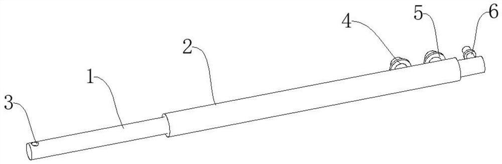
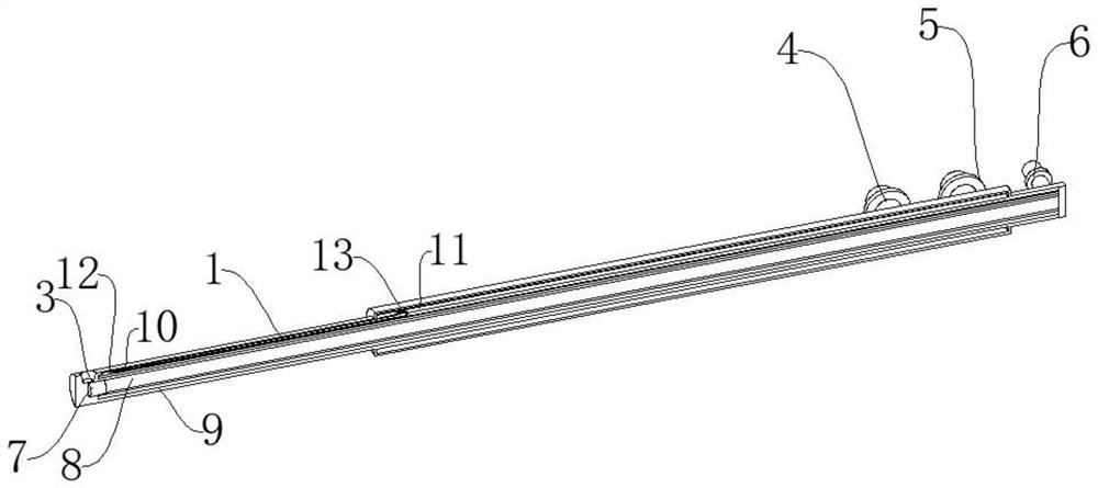
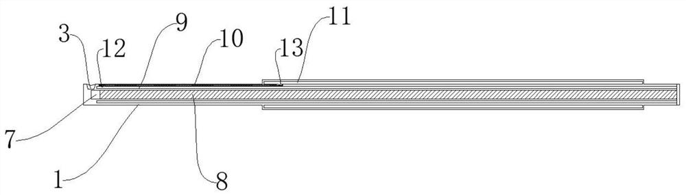
[0028] like Figure 1-Figure 3 As shown, a gas-water composite cooling visualization probe structure includes an inner protective cover 1 for providing air-cooled and water-cooled media and an outer protective cover 2 for displacing return water. The outer rear end of the inner protective cover 1 is provided with an outer protection Cover 2, the top of the inner protective cover 1 is provided with a first optical observation hole 3, the inside of the inner protective cover 1 and the central area of ​​the probe are provided with an air-cooled circulation chamber 8, and the top of the air-cooled circulation chamber 8 is provided with a second optical observation 7, An air-cooling valve 6 is connected to one side of the tail of the air-cooling circulation chamber 8, and a water-cooling water inlet chamber 9 is arranged on the outside of the air-cooling circulation chamber 8 and inside the inner protective cover 1. A water-cooled return chamber 10 is provided inside, and a micro-d...


PUM


Abstract

The invention discloses a gas and water composite cooling visual probe structure, which comprises an inner protective sleeve for providing gas cooling and water cooling media and an outer protective sleeve for replacing return water, the outer protective sleeve is arranged at the rear end of the outer part of the inner protective sleeve, a first optical observation hole is formed in the top end of the inner protective sleeve, a gas cooling circulation cavity is formed in the inner protective sleeve, a second optical observation hole is formed in the top end of the gas cooling circulation cavity, a gas cooling valve is connected to one side of the tail of the gas cooling circulation cavity, a water-cooling water inlet cavity is formed in the outer side of the gas cooling circulation cavity and located in the inner protective sleeve, and a water-cooling water return cavity is formed in the outer side of the water-cooling water inlet cavity and located in the inner protective sleeve. The interior of the probe is of a hollow structure, two cooling media of gas and water are adopted, the water is a closed loop, a heat transfer enhancement micro turbulent flow structure is arranged in the water loop, a gas channel is located in the center area of the probe, and gas flows slowly, so that the temperature of the center area of the probe is suitable for placing an optical camera or an optical fiber.

Description

technical field [0001] The invention relates to the field of visualization probes, in particular to an air-water composite cooling visualization probe structure. Background technique [0002] In the combustion components of power plants such as aero-engines and gas turbines, due to their complex structural characteristics, as well as the high temperature (above 1600K), high pressure, and high-speed combustion environment, it is necessary to measure the cold state, hot state flow field, temperature field and combustion of the combustion chamber. Features are extremely difficult. The use of contact measurement methods such as conventional probes and hot-wire anemometers will often cause certain disturbances to the measured cold and hot flow fields, and only local point parameters can be obtained. At the same time, due to the high temperature and high air velocity in the combustion chamber, the arrangement of probes and hot wires is also very difficult. In recent years, visua...

Claims


Application Information

Patent Timeline
Patent Type & Authority Applications(China)
IPC IPC(8): G01M15/10
CPCG01M15/10
Inventor 陈伟陈鹏飞吴锋
Owner SICHUAN UNIV
Why Eureka
Try Eureka