Rack for optical fiber transmission equipment

An optical fiber transmission and equipment technology, applied in the field of communication equipment, can solve the problems of complicated installation and disassembly, low work efficiency, large labor volume, etc., and achieve the effects of reducing labor intensity, improving work efficiency, and improving use convenience.

Inactive Publication Date: 2021-10-15
北京高科视通科技有限公司
View PDF14 Cites 0 Cited by
  • Summary
  • Abstract
  • Description
  • Claims
  • Application Information

AI Technical Summary

Problems solved by technology

[0005] Aiming at the deficiencies of the prior art, the present invention provides a frame for optical fiber transmission equipment, which has the advantages of easy installation, disassembly and maintenance, etc., and solves the problem of an optical fiber transfer box and prefabricated cabin front wiring with the Chinese patent publication number CN105929505A The screen cabinet has the basic function of installing optical equipment, but its installation uses bolts and threaded holes for fixed connection, resulting in cumbersome installation and disassembly, heavy labor and low work efficiency.

Method used


Image

  • Rack for optical fiber transmission equipment
  • Rack for optical fiber transmission equipment
  • Rack for optical fiber transmission equipment

Examples


Embodiment Construction

[0027] The following will clearly and completely describe the technical solutions in the embodiments of the present invention with reference to the accompanying drawings in the embodiments of the present invention. Obviously, the described embodiments are only some, not all, embodiments of the present invention. Based on the embodiments of the present invention, all other embodiments obtained by persons of ordinary skill in the art without making creative efforts belong to the protection scope of the present invention.

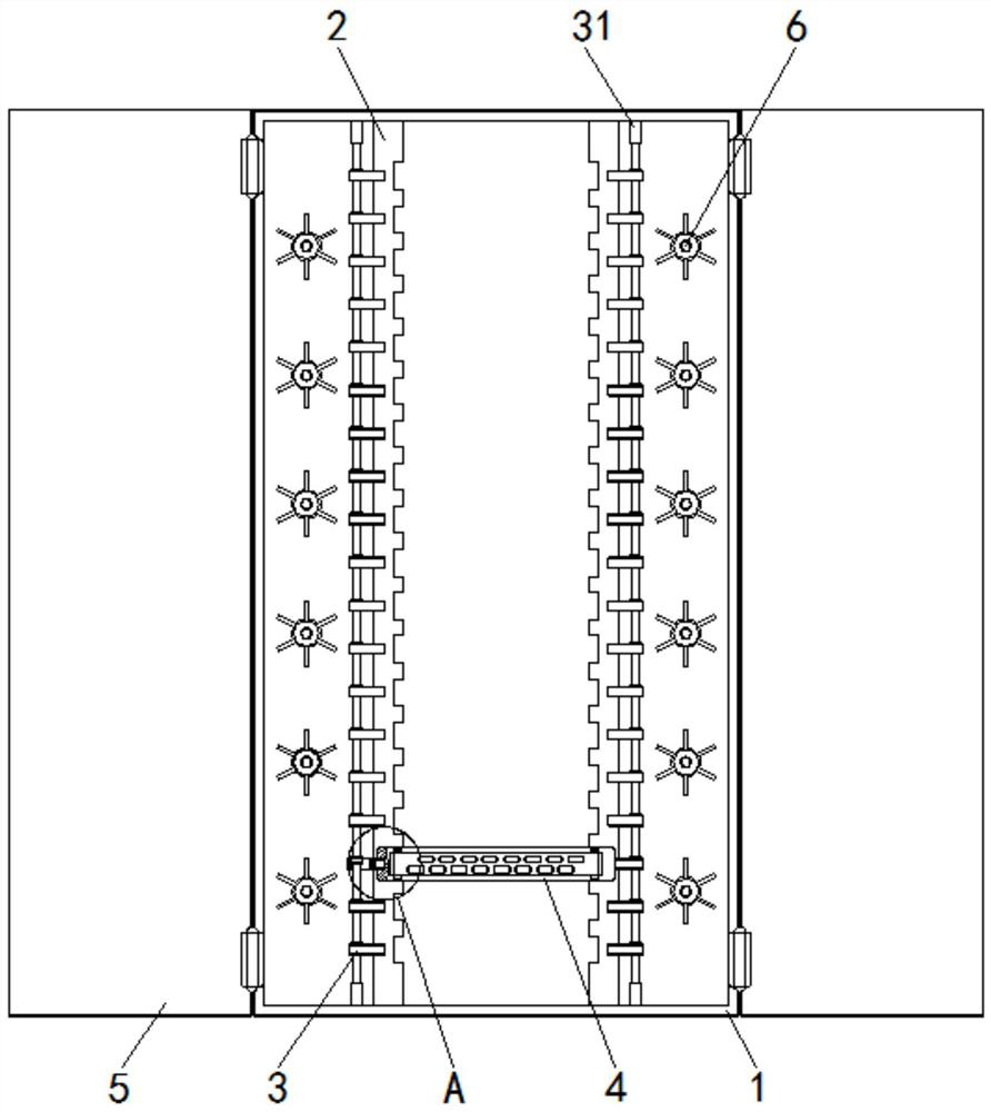
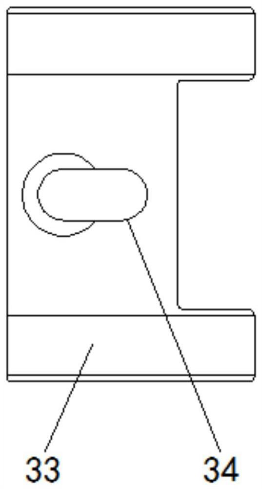
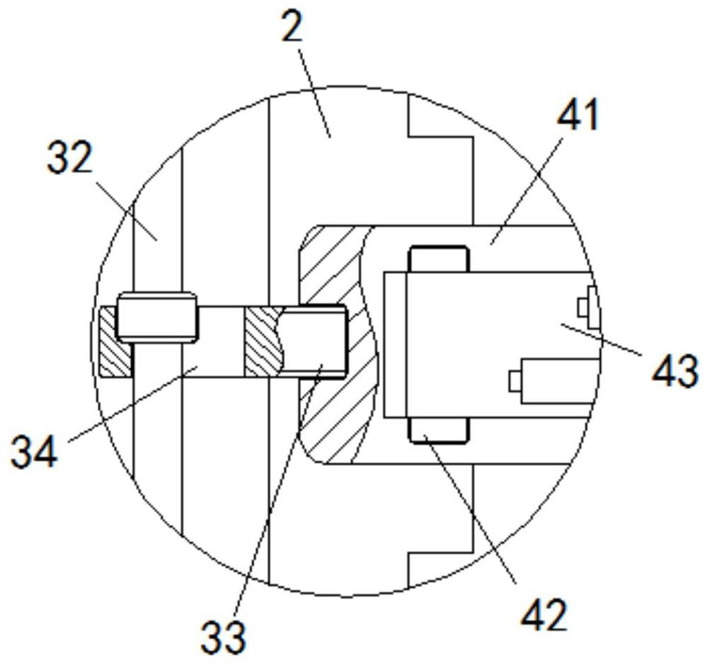
[0028] see Figure 1-4 , a rack for optical fiber transmission equipment, including a box body 1, a mounting frame 2 is fixedly installed on the bottom of the inner wall of the box body 1, and balls 21 are installed in the interior of the mounting frame 2. Adapted positioning slots, the inside of the mounting frame 2 and the outer wall of the ball 21 are movably installed with a limit plate 22, the limit plate 22 is movably connected with the mounting frame 2 ...


PUM


Abstract

The invention relates to the technical field of communication equipment, and discloses a rack for optical fiber transmission equipment, which comprises a box body, a mounting rack is arranged in the box body, positioning mechanisms are arranged in the box body and on the opposite sides of the mounting rack, an optical fiber wire box is arranged in the mounting rack, a box door is arranged on the outer wall of the box body, and a take-up wheel is arranged in the box body. According to the rack for the optical fiber transmission equipment, an optical fiber cable box can be preliminarily positioned up, down, left and right through the mounting grooves in the mounting frame, then the optical fiber cable box can be positioned front and back through the positioning mechanism, and the positioning mechanism can be quickly adjusted without auxiliary tools, so that the optical fiber cable box can be quickly mounted and dismounted; therefore, the installation, disassembly and maintenance period of the optical fiber transmission equipment is greatly shortened, the labor intensity of workers is reduced, the working efficiency is improved, and the effects of simple, convenient and rapid installation, disassembly and maintenance are achieved.

Description

technical field [0001] The invention relates to the technical field of communication equipment, in particular to a frame for optical fiber transmission equipment. Background technique [0002] Optical fiber transmission, that is, data and signal transmission using optical fiber as the medium. Optical fiber can not only be used to transmit analog signals and digital signals, but also can meet the needs of video transmission. Optical fiber transmission is generally carried out using optical cables. The data of a single optical fiber The transmission rate can reach several Gbps, and the transmission distance can reach dozens of kilometers without the use of repeaters. Optical fiber is a technology that uses glass as a waveguide to transmit information from one end to the other in the form of light. Compared with the transmission medium developed in the early stage, the lossy glass fiber is almost not limited by bandwidth and has unique advantages. The point-to-point optical tra...

Claims


Application Information

Patent Timeline
Patent Type & Authority Applications(China)
IPC IPC(8): G02B6/44
CPCG02B6/4446G02B6/4452
Inventor 谷建平
Owner 北京高科视通科技有限公司
Why Eureka
Try Eureka