Eureka AIR delivers breakthrough ideas for toughest innovation challenges, trusted by R&D personnel around the world.

Automatic disinfection type storage device for optical lenses

An automatic disinfection and optical lens technology, applied in the field of optical lenses, can solve problems affecting the health of customers and infection of customers with infectious diseases, and achieve better sterilization and antivirus effects

Active Publication Date: 2021-10-19
泰州晶达光电有限公司
View PDF7 Cites 0 Cited by
  • Summary
  • Abstract
  • Description
  • Claims
  • Application Information

AI Technical Summary

Problems solved by technology

[0003]In the production process, the factory usually puts the produced lenses directly into the storage device for sale. However, in the current period of high incidence of the new crown virus, if the factory Workers carry infectious viruses. These viruses will adhere to the lenses during the lens manufacturing process. When the lenses are sold to customers, they may be infected by contact and may cause customers to be infected with infectious diseases and affect their health. Therefore , how to reasonably solve this problem is what we need to consider

Method used


Image

  • Automatic disinfection type storage device for optical lenses
  • Automatic disinfection type storage device for optical lenses
  • Automatic disinfection type storage device for optical lenses

Examples


Embodiment 1

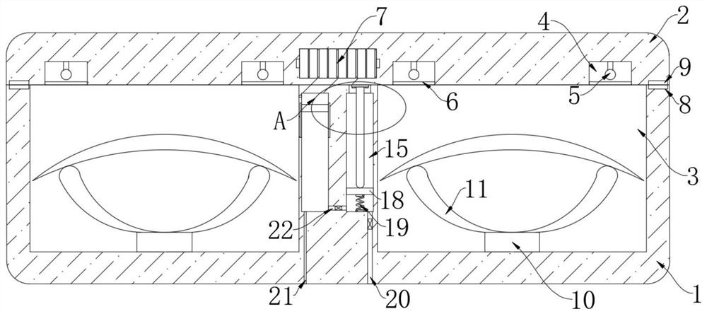
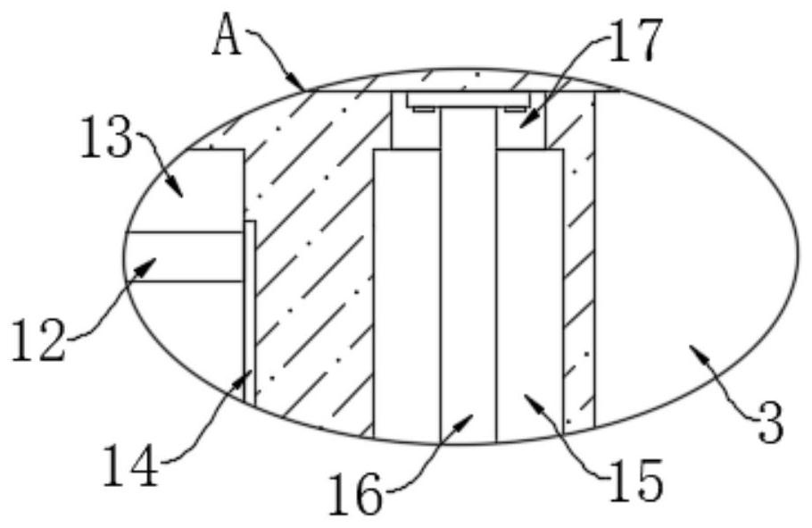
[0024] refer to Figure 1-2 , an automatic disinfection type storage device for optical lenses, comprising a housing 1, a cover plate 2 is arranged on the top of the housing 1, the weight of the cover plate 2 is relatively large, and two placement grooves 3 are arranged symmetrically on the upper end of the housing 1, The housing 1 is provided with 13 vertical cavities 15, the conductive cavity 13 and the vertical cavity 15 are located between the two placement grooves 3, the conductive cavity 13 is located on the left side of the vertical cavity 15, and the lower end of the cover plate 2 is provided with multiple A rectangular slot 4, a power supply 7 is arranged in the cover plate 2, and the power supply 7 is composed of a plurality of electronics;

[0025] The two placement slots 3 are jointly provided with a placement mechanism, the placement mechanism includes two square blocks 10 respectively arranged at the bottom of the two placement slots 3, and the upper ends of the ...

Embodiment 2

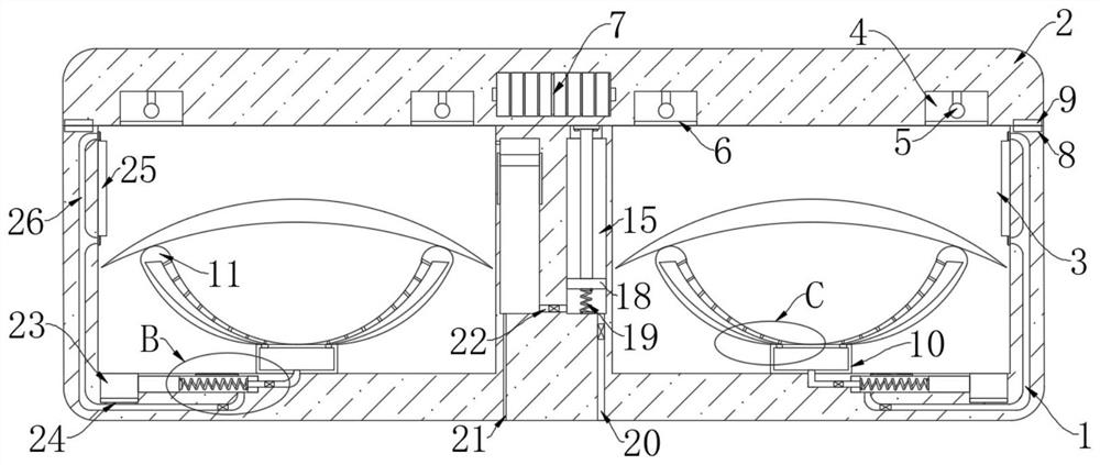
[0040] refer to Figure 3-5 The difference between this embodiment and Embodiment 1 is that the inner bottoms of the two placement grooves 3 are provided with light-shielding grooves 23, and the inner bottoms of the light-shielding grooves 23 are provided with photoresistors 24. When the photoresistors 24 are illuminated, the The resistance value is at the minimum value. When the photoresistor 24 is not exposed to light, the resistance value is at the maximum value. The adjacent sides of the two light-shielding grooves 23 are provided with chute 27, and both chute 27 are provided with The shading block 30, the shading block 30 is made of opaque material, the two shading blocks 30 are magnetic, the two shading blocks 30 are slidingly connected with the inner walls of the corresponding chute 27, and the two chute 27 is away from the corresponding shading One side inwall of groove 23 is all equipped with electromagnet 36, and power supply 7, the conductive sheet 14 that is positi...


PUM


Abstract

The invention discloses an automatic disinfection type storage device for the optical lenses, which comprises a shell, a cover plate is arranged above the shell, two placement grooves are symmetrically formed in the upper end of the shell, a conductive cavity and a vertical cavity are formed in the shell, the conductive cavity and the vertical cavity are located between the two placement grooves, the conductive cavity is located on the left side of the vertical cavity, a plurality of rectangular grooves are formed in the lower end of the cover plate, a power source is arranged in the cover plate, a placing mechanism is jointly arranged in the two placing grooves, the placing mechanism comprises two square blocks arranged at the bottoms in the two placing grooves respectively, and two arc-shaped plates are symmetrically installed at the upper ends of the two square blocks. According to the device, the optical lens is sterilized and disinfected through the ultraviolet lamp, the situation that consumers are infected with diseases due to the fact that the lens is contaminated with viruses in the production process is avoided, meanwhile, part of oxidizing substances generated by the photocatalyst plate are sprayed to the bottom of the lens through airflow, and therefore the sterilization and disinfection effect on the lens is better.

Description

technical field [0001] The invention relates to the technical field of optical lenses, in particular to an automatic disinfection storage device for optical lenses. Background technique [0002] With the continuous development of optical lenses, it has also brought great convenience to people's lives. Because optical lenses involve many important areas in life, especially in shooting and video recording, they are deeply loved by people. When the factory manufactures optical lenses, it will store the lenses in storage boxes before selling them. However, the existing optical lens storage devices still have the following problems during use: [0003] During the production process, the factory usually puts the produced lenses directly into the storage device for sale. However, in the current period of high incidence of the new crown virus, if the workers in the factory carry the infectious virus, these viruses will be lost during the lens manufacturing process. It will adhere t...

Claims


Application Information

Patent Timeline
Patent Type & Authority Applications(China)
IPC IPC(8): A61L2/10A61L2/24A61L2/26
CPCA61L2/10A61L2/24A61L2/26A61L2202/14
Inventor 李奕民
Owner 泰州晶达光电有限公司
Why Eureka
Eureka Blog
Learn More