
Electric tool

A technology of electric tools and tools, applied in the direction of manufacturing tools, portable mobile devices, etc., can solve the problems of inability to meet the high heat dissipation requirements of the outer rotor motor and the high heat dissipation requirements of the outer rotor motor, so as to improve the air outlet efficiency, solve the heat dissipation problem, and improve the The effect of heat dissipation

Pending Publication Date: 2021-10-19
POSITEC POWER TOOLS (SUZHOU) CO LTD
View PDF0 Cites 0 Cited by
  • Summary
  • Abstract
  • Description
  • Claims
  • Application Information

AI Technical Summary

Problems solved by technology

The motors of cutting tools usually include inner rotor motors and outer rotor motors. At present, conventional cutting tools often use inner rotor motors, but compared with inner rotor motors, outer rotor motors have the advantages of small size and large torque, but there are The problem of high heat dissipation requirements, so the current conventional cutting tools cannot meet the high heat dissipation requirements of external rotor motors in terms of heat dissipation

Method used


Image

  • Electric tool
  • Electric tool
  • Electric tool

Examples


Embodiment Construction

[0021] The specific implementation manners of the present invention will be further described in detail below in conjunction with the accompanying drawings and embodiments. The following examples are used to illustrate the present invention, but are not intended to limit the scope of the present invention.

[0022] The technical solutions of the present invention will be clearly and completely described below in conjunction with the accompanying drawings. Apparently, the described embodiments are some of the embodiments of the present invention, but not all of them. Based on the embodiments of the present invention, all other embodiments obtained by persons of ordinary skill in the art without making creative efforts belong to the protection scope of the present invention.

[0023] In the description of the present invention, it should be noted that the terms "center", "upper", "lower", "left", "right", "vertical", "horizontal", "inner", "outer" etc. The indicated orientation...


PUM


Abstract

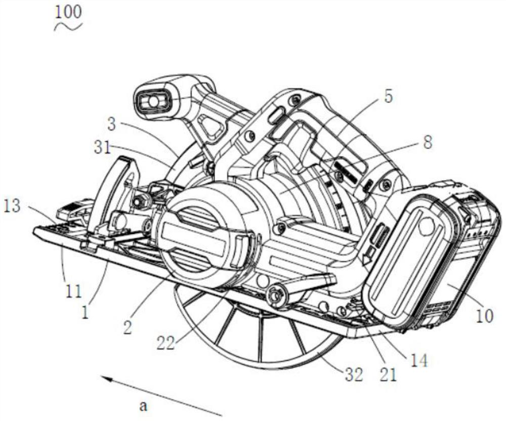
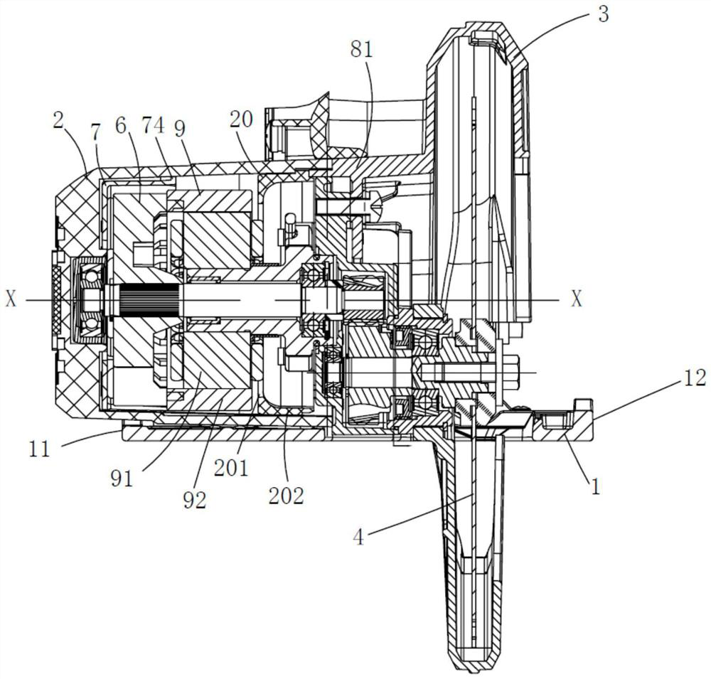
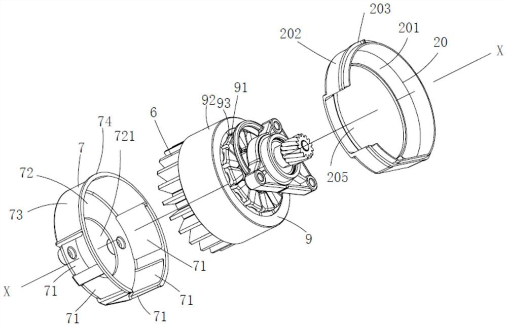
The invention relates to an electric tool, in particular to a cutting tool. The electric tool comprises a functional part used for achieving tool functions, a motor used for driving the functional part to operate, a fan arranged on one side of the motor and a motor shell used for containing the motor, wherein the motor is an external rotor motor, the electric tool further comprises an airflow guiding device arranged on the outer side of the fan in a surrounding mode, an air outlet is formed in the airflow guiding device, the airflow guiding device is provided with an arc-shaped air guiding side wall, the air guiding side wall is provided with a first end close to one side of the air outlet and a second end opposite to the first end, and the linear distance from the air guiding side wall to the central axis of the fan is gradually reduced from the first end to the second end.

Description

technical field [0001] The invention relates to an electric tool, especially a cutting tool. Background technique [0002] The cutting tool is used to realize the cutting function, and has the characteristics of safety, reliability and high work efficiency. The cutting tool is mainly composed of a motor, a gearbox, a shield assembly, a base plate, and an electric control system. The motors of cutting tools usually include inner rotor motors and outer rotor motors. At present, conventional cutting tools often use inner rotor motors, but compared with inner rotor motors, outer rotor motors have the advantages of small size and large torque, but there are The problem of high heat dissipation requirements, so the current conventional cutting tools cannot meet the high heat dissipation requirements of external rotor motors in terms of heat dissipation. Contents of the invention [0003] The purpose of the present invention is to provide an electric tool that can adopt an exte...

Claims


Application Information

Patent Timeline
Patent Type & Authority Applications(China)
IPC IPC(8): B25F5/00
CPCB25F5/008
Inventor 吉绍山张响亮刘兵建
Owner POSITEC POWER TOOLS (SUZHOU) CO LTD
Learn More