Float glass surface coating device and use method
A surface coating, float glass technology, applied in the direction of coating, can solve the problems of uncontrolled temperature, environmental pollution, unable to meet the requirements of spraying process, etc., to achieve the effect of improving quality
- Summary
- Abstract
- Description
- Claims
- Application Information
AI Technical Summary
Problems solved by technology
Method used
Image

Examples
Embodiment Construction
[0031] The present invention is described in conjunction with accompanying drawing and specific embodiment:
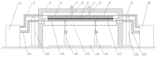
[0032] Such as figure 1Shown, a kind of float glass surface coating device, coating device comprises left upper sprayer 4, right upper sprayer 8, left lower sprayer 13, right lower sprayer 17; Left upper sprayer 4 and right upper sprayer 8 linear connection composition The upper sprayer, above the glass plate 6, sprays a gas protective layer on the surface of the glass plate, and the lower left sprayer 13 and the lower right sprayer 17 are connected in a straight line to form the lower sprayer, which is below the glass plate, sprays gas on the lower surface of the glass plate 6 The protective layer, the upper and lower sprayers are all installed in the steel shell 3 of the annealing kiln. The upper sprayer is hoisted above the glass plate 6 by the screw ring 5 and the nut group 7, and the lower sprayer is supported under the glass plate 6 by the lifting support rod 14...
PUM
 Abstract
Description
Claims
Application Information
 - R&D
- Intellectual Property
- Life Sciences
- Materials
- Tech Scout
- Unparalleled Data Quality
- Higher Quality Content
- 60% Fewer Hallucinations
Browse by: Latest US Patents, China's latest patents, Technical Efficacy Thesaurus, Application Domain, Technology Topic, Popular Technical Reports.
© 2025 PatSnap. All rights reserved.Legal|Privacy policy|Modern Slavery Act Transparency Statement|Sitemap|About US| Contact US: help@patsnap.com