Power transmission device with working part height difference compensation function

A technology for power transmission devices and working parts, applied in the direction of transmission devices, transmission device parts, energy-saving measures, etc., can solve the problems of increasing equipment investment costs, increasing the difficulty of daily use management and maintenance, etc., to achieve reasonable structure and save equipment investment costs , the effect of simplifying the structure

Active Publication Date: 2021-10-19
常熟得美零部件有限公司
View PDF7 Cites 0 Cited by
  • Summary
  • Abstract
  • Description
  • Claims
  • Application Information

AI Technical Summary

Problems solved by technology

In addition, since the aforementioned power transmission device in the prior art can only drive one load (that is, only one kind of working parts can be driven to work), the more the load, the more the number of machines and their power transmission devices, so on the one hand Increased the burden of equipment input costs in the garden and agricultural sectors, and on the other hand increased the difficulty of management and maintenance in daily use

Method used


Image

  • Power transmission device with working part height difference compensation function
  • Power transmission device with working part height difference compensation function
  • Power transmission device with working part height difference compensation function

Examples


Embodiment Construction

[0020] In order to be more clearly understood, the applicant will be described in detail in the manner described below, but the description of the present invention is not limited to the embodiments of the present invention. It is only the technical solution category of the present invention only for the form of the present invention.

[0021] In the following description, the concept involving the direction, lower, left, and right, and then rear, and the corresponding direction is based in addition to the other description. figure 1 The state is based, and thus it is not understood to be particularly limited in the technical solutions provided by the present invention.

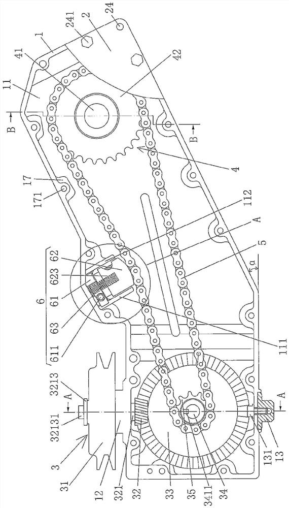
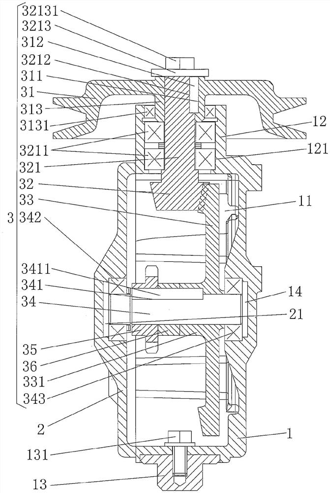
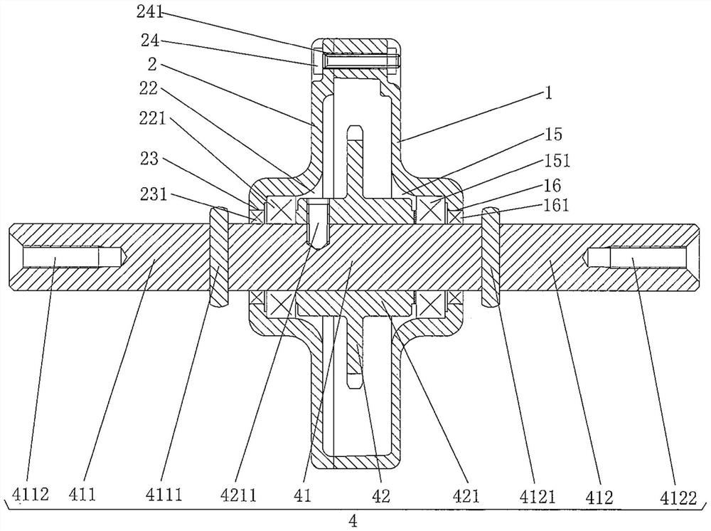
[0022] See figure 1 A replacement case housing 1 and a replacement case cover 2 are shown, and the replacement case housing 1 has a housing chamber 11, the replacement case cover 2 is corresponding to the position of the casing cavity 11 and the gear case housing. 1 fixed; showing a power input transmission mechan...


PUM


Abstract

The invention discloses a power transmission device with a working part height difference compensation function, and belongs to the technical field of gardens and agricultural facilities. The power transmission device comprises a reduction gearbox shell, a reduction gearbox shell cover and a speed reduction transmission chain, the reduction gearbox shell is provided with a shell cavity, and the reduction gearbox shell cover is fixed to the reduction gearbox shell; a power input transmission mechanism is arranged between the reduction gearbox shell and the left end of the reduction gearbox shell cover, and the power output transmission mechanism is arranged between the reduction gearbox shell and the right end of the reduction gearbox shell cover; the left end of the speed reduction transmission chain is in transmission connection with the power input transmission mechanism, and the right end of the speed reduction transmission chain is in transmission connection with the power output transmission mechanism. The power transmission device has the following characteristics: the left end of the reduction gearbox shell and the left end of the reduction gearbox shell cover form a rectangular structure, the right end of the reduction gearbox shell and the right end of the reduction gearbox shell cover are raised upwards, and a working part height difference compensation angle is formed between the right end of the reduction gearbox shell and the right end of the reduction gearbox shell cover and the bottom plane of the left end of the reduction gearbox shell and the left end of the reduction gearbox shell cover. The power transmission device has the following advantages: the structure is simplified, equipment investment cost is saved, and daily management and protection difficulty is reduced.

Description

Technical field [0001] The present invention belongs to the technical field of gardens and agricultural facilities, and more particularly to a power transmission device having a highly differential compensation function of the working component. Background technique [0002] Typical examples of the aforementioned working parts, such as sweeping snow rollers, snow blade wheels, mowers rollers, hoe rollers and loop rollers, etc. Working components are generally high in linear gearboxes between the category of the motor belonging to the motor transmission (by the floor level of the floor), which requires the aforementioned aforementioned Highly poor compensation. Further, since the foregoing power transmission in the prior art can only be driven (i.e., only one working component can be moved), the more loads, the number of the machine and its power transmission, therethrough, on one aspect Increase the burden on the investment cost of gardens, agricultural sector equipment, and on t...

Claims


Application Information

Patent Timeline
IPC IPC(8): F16H37/06F16H57/021F16H57/023F16H57/025F16H57/029F16H57/031F16H7/08
CPCF16H37/065F16H57/021F16H57/023F16H57/025F16H57/029F16H57/031F16H7/0838Y02P60/14
Inventor 言奕王朱裔言行周陆玉兰
Owner 常熟得美零部件有限公司
Why Eureka
Try Eureka