Turbomolecular vacuum pump and purging method

A turbomolecular and vacuum pump technology, applied to pumps, pump components, axial flow pumps, etc., to achieve the effect of prolonging time and increasing flow

Pending Publication Date: 2021-10-19
PFEIFFER VACUUM GMBH
View PDF10 Cites 0 Cited by
  • Summary
  • Abstract
  • Description
  • Claims
  • Application Information

AI Technical Summary

Problems solved by technology

Heating the stator to these temperatures does effectively reduce the formation of deposits in the pump, but it does not completely prevent this, especially in the case of certain chemicals such as AlCl 3

Method used


Image

  • Turbomolecular vacuum pump and purging method
  • Turbomolecular vacuum pump and purging method
  • Turbomolecular vacuum pump and purging method

Examples


Embodiment Construction

[0038] The following embodiments are examples. Although the description refers to one or more embodiments, this does not necessarily mean that every reference refers to the same embodiment or that a feature applies uniquely to a single embodiment. Individual features of various embodiments can be equally combined or interchanged to form other embodiments.

[0039] "Upstream" means that one element is located before another element with respect to the direction of gas circulation. Conversely, "downstream" means that one element is located behind another element with respect to the direction of circulation of the gas to be pumped, the upstream element being at a lower pressure than the downstream element.

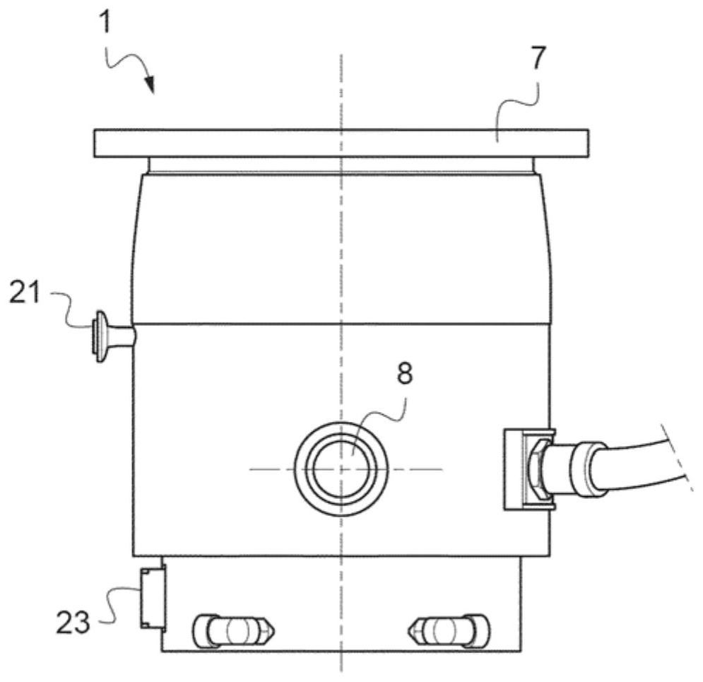
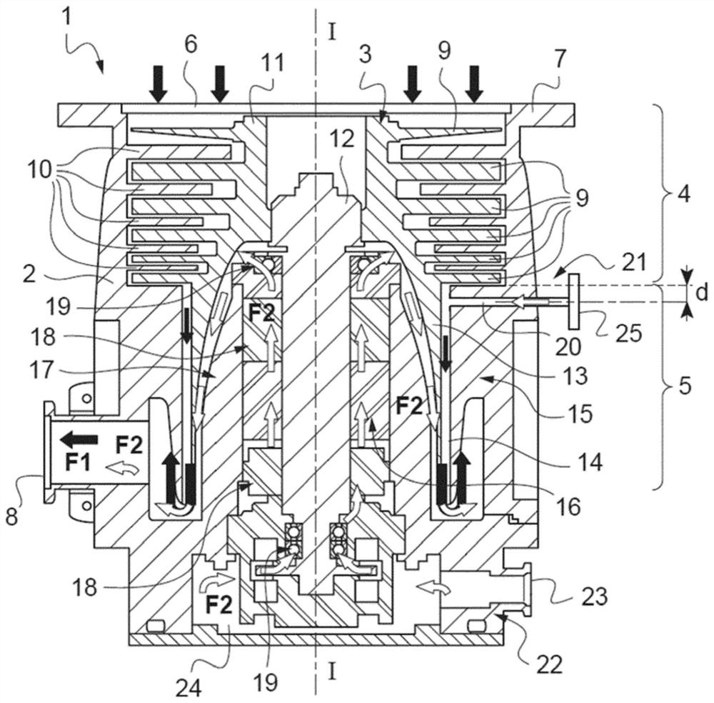
[0040] figure 1 and figure 2 A first embodiment of a turbomolecular vacuum pump 1 is shown.

[0041] The turbomolecular vacuum pump 1 includes a stator 2 in which a rotor 3 is configured to rotate axially at high speed, for example at a speed exceeding 20,000 revolutions...


PUM


Abstract

The present invention concerns a turbomolecular vacuum pump (1) comprising a device for injecting purge gas (21) comprising at least one channel (20) provided in the stator (2) and emerging between the rotor (3) and the stator (2), for injecting a purge gas into a path of the pumped gases, downstream from at least one stage of blades (9) of the rotor (3), the device for injecting purge gas (21) being configured such that the flow rate of the injected purge gas is lower than a predetermined threshold such that the pressure difference between a suction side (6) without injection of the purge gas and with injection of a purge gas is lower than 0.066 Pa. The invention also relates to a method for purging a turbomolecular vacuum pump (1).

Description

technical field [0001] The invention relates to a turbomolecular vacuum pump and to a method for cleaning a turbomolecular vacuum pump. Background technique [0002] Generating a high vacuum in the chamber requires the use of a turbomolecular vacuum pump, which includes a stator in which a rotor is driven into rapid rotation, for example at speeds in excess of 20,000 revolutions per minute. [0003] In certain processes using turbomolecular vacuum pumps, for example in the manufacture of semiconductors or LEDs, a deposit may form in the vacuum pump. This deposit can cause the gap between the stator and rotor to become restricted, which can cause the rotor to stall. This layer of deposits actually heats the rotor by friction, which may cause it to creep and possibly rupture. [0004] It is known practice to heat the stator to prevent condensation of reaction products in the pump. However, to maintain the mechanical integrity of the rotor, the temperature to which the stato...

Claims


Application Information

Patent Timeline
Patent Type & Authority Applications(China)
IPC IPC(8): F04D19/04F04D29/70
CPCF04D19/042F04D29/701F05D2260/607
Inventor N·瓦雷纳A·当格勒维尔
Owner PFEIFFER VACUUM GMBH
Why Eureka
Try Eureka