Hydraulic retarder control system

A technology of hydraulic retarder and control system, applied in hydraulic brakes, hydraulic resistance brakes, brake types, etc., can solve problems such as inability to quickly control the accuracy of water temperature, unfavorable driver operation, and decrease in retarder torque.

Pending Publication Date: 2021-10-22
吉林省中誉信德科技有限公司
View PDF0 Cites 2 Cited by
  • Summary
  • Abstract
  • Description
  • Claims
  • Application Information

AI Technical Summary

Problems solved by technology

[0002] At present, the existing retarders in the market are all caused by the high water temperature, which leads to the decrease of the retarder torque, which leads to insufficient braking torque, or the driver manually reduces the transmission gear to increase the engine speed, so that the vehicle's heat dissipation capacity increases, and the manual method can be used to increase the speed of the engine. The heat dissipation capacity of the whole vehicle can not quickly control the accuracy of low or high water temperature, and it is not conducive to the driver's operation. With the emergence of automatic transmissions, it is impossible to improve the heat dissipation of the whole vehicle by manually reducing the transmission gear and increasing the engine speed. Finish

Method used


Image

  • Hydraulic retarder control system
  • Hydraulic retarder control system

Examples


Embodiment 1

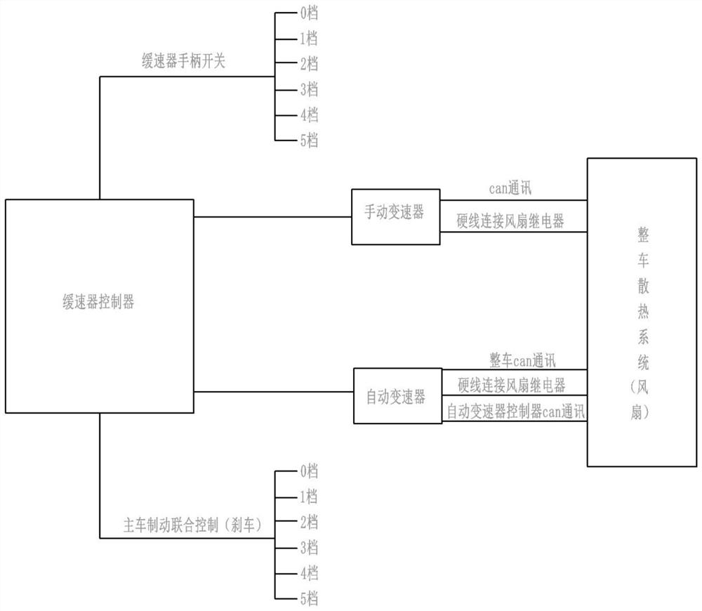
[0026] Basic as attached figure 1 Shown: a hydraulic retarder control system, including a retarder controller, a retarder handle switch, a main vehicle braking system and a complete vehicle cooling system.

[0027] In this embodiment, the retarder controller is the controller ECU, and the retarder handle switch is provided with several gears, and the several gears are: 0 gear, 1 gear, 2 gear, 3 gear, 4 gear, and 5 gear. The retarder handle switch is installed on the right side of the car dashboard or on the right side of the steering wheel (not shown in the figure).

[0028] The main vehicle braking system is an existing automobile braking system. This embodiment is: a braking system. The braking system includes a brake light for prompting the opening and closing of the main vehicle braking system. The braking system has 0 gears, 1 gears, and 2 gears. , 3rd gear, 4th gear, 5th gear, the braking strength of different gears is different. The vehicle heat dissipation system is ...

Embodiment 2

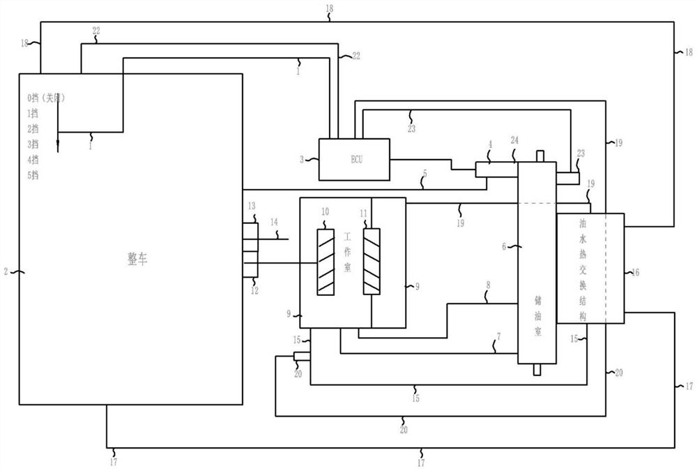
[0039] The difference between embodiment two and embodiment one is that, as attached figure 2 As shown, the retarder controller in this embodiment is the controller ECU3, and the retarder handle switch 1 is installed on the right side of the automobile instrument panel or on the right side of the steering wheel. The electromagnetic proportional valve 4 between the transmission and the vehicle, the electromagnetic proportional valve 4 communicates with the air system of the vehicle cooling system through the pipeline 5.

[0040]The electromagnetic proportional valve 4 communicates with the oil storage chamber 6 of the hydraulic retarder. In the present embodiment, the upper part of the oil storage chamber 6 is a cavity, and a pressure detection device 23 electrically connected to the controller ECU3 is installed in the cavity (pressure sensor), the oil storage chamber 6 below is an oil storage chamber, the cavity is provided with an exhaust port 24, and an air outlet valve is ...


PUM


Abstract

The invention relates to the technical field of hydraulic retarders, and discloses a hydraulic retarder control system. The system comprises a retarder controller, a retarder handle switch, a main vehicle braking system and a whole vehicle cooling system; the main vehicle braking system sends braking information to the retarder controller, and the retarder controller controls the braking torque of the hydraulic retarder based on the braking information; the retarder controller acquires liquid temperature information of the hydraulic retarder, and based on the water temperature information, the retarder controller controls a whole vehicle cooling system; and the retarder handle is provided with a plurality of gears, and the retarder controller controls the braking torque of the hydraulic retarder based on gear information. The hydraulic retarder is cooled, and the braking torque of the hydraulic retarder is improved.

Description

technical field [0001] The invention relates to the technical field of hydraulic retarders, and specifically discloses a hydraulic retarder control system. Background technique [0002] At present, the existing retarders in the market are all caused by the high water temperature, which leads to the decrease of the retarder torque, which leads to insufficient braking torque, or the driver manually reduces the transmission gear to increase the engine speed, so that the vehicle's heat dissipation capacity increases, and the manual method can be used to increase the speed of the engine. The heat dissipation capacity of the whole vehicle can not quickly control the accuracy of low or high water temperature, and it is not conducive to the driver's operation. With the emergence of automatic transmissions, it is impossible to improve the heat dissipation of the whole vehicle by manually reducing the transmission gear and increasing the engine speed. Finish. Contents of the inventi...

Claims


Application Information

Patent Timeline
Patent Type & Authority Applications(China)
IPC IPC(8): B60T10/02B60T7/10B60Q1/44F16D57/00F16D65/78
CPCB60T10/02B60T7/10B60Q1/44F16D57/00F16D65/78F16D2065/783
Inventor 传海军王键张士城
Owner 吉林省中誉信德科技有限公司
Why Eureka
Try Eureka